Renewal clearances, Disassembly, Disassembly (6.9) – Flowserve IDP CPXV User Manual
Page 27: Dismantling (6.9, disassembly), 8 renewal clearances, 9 disassembly
CPXV and CPXRV USER INSTRUCTIONS ENGLISH 71569193 09-14
Page 27 of 48
flowserve.com
b)
Some mechanical seal types may be
impaired if moved more than 0.5 mm (0.02 in.)
from their nominal setting.
c) Disconnect the coupling if it has limited axial
flexibility.
d) Record the gap between the bearing carrier
[3240.1] and motor pedestal [3160.1] using feeler
gauges.
6.7.1
For CPXV pumps only
e)
Loosen the bearing carrier screws [6570.3] and
back off the bearing carrier by 2 mm (0.08 in.)
using screws [6570.4].
f)
Tighten the bearing carrier screws [6570.3] evenly,
drawing the bearing carrier towards the sole plate,
until the impeller contacts the pump casing. Turn the
shaft [2100], during this procedure, until a detectable
rub is obtained. This is the zero clearance position.
The shaft must be turned in the direction
indicated on the casing and sole plate.
g)
Set a dial indicator to zero on the shaft end or
measure the bearing carrier [3240.1] to motor
pedestal [3160.1] gap and record the
measurement.
h)
Slacken the bearing carrier screws [6570.3].
i)
Tighten screws [6570.4] evenly (about one flat at a
time) until the dial indicator or feeler gauge shows
the correct impeller clearance from the zero
clearance position. This clearance should be
between 0.3 and 2mm (0.012 and 0.080 in.)
depending on the nature of the pumped fluid.
6.7.2
For CPXRV (recessed impeller) only
e) The impeller does not have a fine front clearance
setting and adjustment of the impeller is not
normally required
f)
Loosen the bearing carrier nuts and screws and
back off the bearing carrier jacking screws by
2 mm (0.08 in).
g)
Tighten the bearing carrier screws [6570.4] evenly,
pushing the bearing carrier away from the sole plate,
until the impeller contacts the cover. Turn the shaft
[2100], during this procedure, until a detectable rub
is obtained. This is the zero clearance position.
The shaft must be turned in the direction
indicated on the casing and sole plate.
h) Set a dial indicator to zero on the shaft end or
measure the bearing carrier [3240.1] to motor
pedestal [3160.1] gap and record the measurement.
i)
Tighten the bearing carrier [6570.3] screws evenly
(about one flat at a time) until the dial indicator or
feeler gauge shows the correct impeller clearance
from the zero clearance position.
6.7.3
For CPXV and CPXRV
j)
Evenly tighten the bearing carrier screws [6570.3]
keeping the dial indicator or feeler gauges reading
the correct setting. Then tighten the hexagon nuts
[6580.1] to lock the jacking screws in position.
k)
Compare the original and final gaps between the
bearing carrier and sole plate to check if the
movement of the shaft has exceeded the seal
capability (over/under compression of the seal).
Re-position the seal to correct this
l)
Check that the shaft can turn freely without binding.
m)
If a cartridge seal is fitted, reset it at this point.
n)
Ensure the coupling distance between shaft ends
(DBSE) is correct. Reset/re-align if necessary.
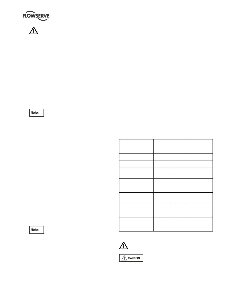
6.8 Renewal clearances
As wear takes place between the impeller and casing
ring the overall efficiency of the pump set will
decrease. To maintain optimum efficiency it is
recommended that the clearances shown in section
6.7, Setting impeller clearance, are maintained.
On product lubricated bearings it is recommended
that these are renewed at the diametrical clearance in
the as fitted condition stated in the following table:
Bearing sleeve size
mm (in.)
Sleeve
diameter/tolerance
min diam - max diam
mm (in.)
Bearing clearance
(max/min)
mm (in.)
Fr1/2 silicon carbide
54 (2.125)
53.87
(2.1209)
53.89
(2.1217)
0.13/0.085
(0.0051/0.0033)
Fr3/4 silicon carbide
79 (3.110)
78.85
(3.1043)
78.87
(3.1051)
0.18/0.13
(0.0071/0.0051)
Fr1 pump end bush in
engineering polymer
35 (1.375)
34.98
(1.3772)
35.00
(1.3780)
0.31/0.15
(0.0122/0.0059)
Fr1 intermediate and Fr2
pump end bushes in
engineering polymer
45 (1.770)
44.98
(1.7709)
45.00
(1.7717)
0.35/0.19
(0.0138/0.0075)
Fr3 pump end bush in
engineering polymer
65 (2.559)
64.98
(2.5583)
65.00
(2.5591)
0.41/0.25
(0.0161/0.0098)
Fr2/3 intermediate
bushes in engineering
polymer
65 (2.559)
64.98
(2.5583)
65.00
(2.5591)
0.39/0.23
(0.0154/0.0091)
Fr4 pump end and
intermediate bush in
engineering polymer
70 (2.7559)
69.98
(2.5583)
70.00
(2.7559)
0.39/0.23
(0.0154/0.0091)
6.9 Disassembly
Refer to Safety, section 1.6, before dismantling
the pump.
Before dismantling the pump for
overhaul, ensure genuine Flowserve replacement
parts are available.