Spare parts, Recommended spares, Tools required – Flowserve IDP CPXV User Manual
Page 25: Replacement parts (6.3 and 6.4), Spare parts (6.3), Tools required (6.5), 3 spare parts, 4 recommended spares, 5 tools required
CPXV and CPXRV USER INSTRUCTIONS ENGLISH 71569193 09-14
Page 25 of 48
flowserve.com
6.2.4
Mechanical seals
When leakage becomes unacceptable the seal will
need replacement.
6.2.5
Gland packing
Pump must be stopped and
electrically isolated when replacing gland packing.
There is a fan above the packing, close by, on all
high temperature builds of the pump.
On hot molten salt service nitrogen is fed with three
rings of metal packing and Nitrogen will leak across the
packing for cooling purposes.
Occasionally, a new ring of packing will be required to
keep the box full.
On jacketed molten sulphur pumps the stuffing box is
normally supplied with a lantern ring to enable it to be
lubricated to the centre of the packing with the required
Molykote 44 Medium or equivalent grease from a
Staufer or equivalent.
6.3 Spare parts
6.3.1
Ordering of spares
Flowserve keeps records of all pumps that have been
supplied. When ordering spares the following
information should be quoted.
1)
Pump serial number.
2)
Pump size.
3)
Part name – taken from section 8.
4)
Part number – taken from section 8.
5)
Number of parts required.
The pump size and serial number are shown on the
pump nameplate.
To ensure continued satisfactory operation,
replacement parts to the original design specification
should be obtained from Flowserve. Any change to
the original design specification (modification or use
of a non-standard part) will invalidate the pump’s
safety certification.
6.3.2
Storage of spares
Spares should be stored in a clean dry area away
from vibration. Inspection and re-treatment of
metallic surfaces (if necessary) with preservative is
recommended at 6 monthly intervals.
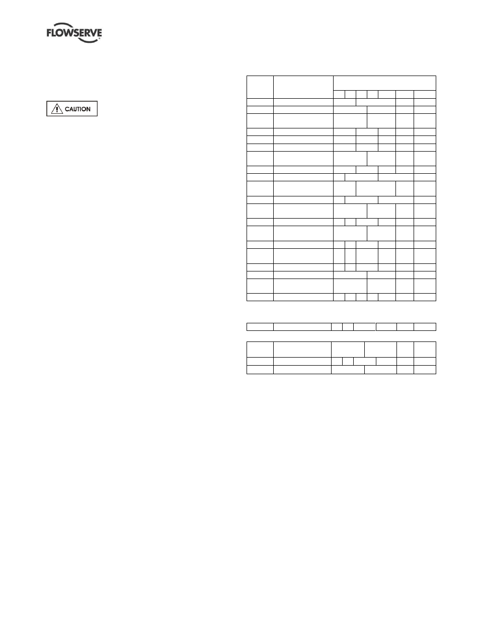
6.4 Recommended spares
(For two years operation - as per VDMA 24296)
Part
no.
Designation
Number of pumps
(including stand-by)
2 3 4 5 6/7
8/9 10(+)
2100
Shaft
1
2
3
30%
2200
Impeller
1
2
3
30%
2400.1
Shaft sleeve - pump
end
2
3
4
50%
3013
Bearing - thrust
1
2
3
4
50%
3300.1 Bearing - pump end
1
2
3
4
50%
3300.2 Bearing - lineshaft *
1
2
3
4
50%
3400.1
Shaft sleeve -
intermediate *
2
3
4
50%
3712
Bearing nut
1
2
3
4
50%
4120
Lantern halves *
1
2
3
30%
4130
Gland packing -
complete set *
2
3
4
40%
4200
Mechanical seals *
1
2
3
30%
2400.2
Sleeve - mechanical
seal *
2
3
4
50%
4305
Lip seal *
4 6
8
9
10
100%
6570.9
Shaft sleeve screw
for 3400.1 *
2
3
4
50%
4590.1** Pump casing gasket 4 6
8
9
12
150%
4590.2
Discharge flange
gasket
4 6
8
9
12
150%
4610.1 O-ring impeller
4 6
8
9
12
150%
4610.2 O-ring carrier
2
3
4
50%
4610.3
O-ring mechanical
seal sleeve *
2
3
4
50%
-
Power end
-
-
-
-
-
1
2
* When required due to fitting as part of the original build specification.
** Note: for CPXRV replace by the following:
4590.1 Pump casing gasket 8 12
16
18
24 300%
Additional spares for keyed impeller option
2912.1/
2912.2
Impeller nut
1
2
3
30%
4610.5 O-ring impeller
4 6
8
9
12 150%
6700.2 Impeller key
1
2
3
30%
6.5 Tools required
A typical range of tools that will be required to
maintain these pumps is listed below:
Readily available in standard tool kits, and dependent
on pump size:
Open ended spanners (wrenches) to suit up to
M 48 screws/nuts
Socket spanners (wrenches), up to M 48 screws
Allen keys, up to 10 mm (A/F)
Range of screwdrivers
Soft mallet
More specialized equipment:
Bearing pullers
Bearing induction heater
Dial test indicator
C-spanner (wrench) - for removing shaft nut.
(If difficulties in sourcing are encountered, consult
Flowserve.)