Casing, seal housing and fastener torques, Setting impeller clearance, 6 casing, seal housing and fastener torques – Flowserve IDP CPXV User Manual
Page 26: 7 setting impeller clearance
CPXV and CPXRV USER INSTRUCTIONS ENGLISH 71569193 09-14
Page 26 of 48
flowserve.com
6.6 Casing, seal housing and fastener
torques
Fastener
Screw size
Torque Nm (lb•ft)
All except where
otherwise stated
M8
M10
M12
M16
M20
16 (12)
25 (18)
35 (26)
80 (59)
130 (96)
Impeller nut
M12
M16
M22
M24
16 (12)
41 (31)
106 (79)
135 (100)
Above apply for applications below
250 ºC only and not in the range 250 ºC to 600
ºC.
Non-metallic gaskets incur creep
relaxation - before commissioning the pump check
and retighten fasteners to tightening torques stated.
Below lower values apply for
applications
in the high temperature range of 250 ºC to
600
ºC.
Bolt torque values for class 2 lubricated threads
Thread data
Material group
A
316 SS
B
ASTM A193
Grade B7M
4140 Steel
C
ASTM A193
Grade B8C
347H SS
Approximate yield stress N/mm
2
(psi)
Nominal
diameter
mm (in.)
Threads
per
25 mm
(1 in.)
207
(30 000)
(<400 ºC)
552
(80 000)
(<400 ºC)
138
(20 000)
(400 to
600 ºC)
Torque Nm (lb
•ft)
6 (0.25)
20
4 (3)
9 (7)
3 (2)
8 (0.31)
18
7 (5)
17 (13)
5 (3)
10 (0.37)
16
9 (7)
27 (20)
8 (6)
11 (0.43)
14
16 (12)
42 (31)
15 (11)
12 (0.5)
13
23 (17)
62 (46)
20 (15)
15 (0.56)
12
27 (20)
89 (66)
27 (20)
16 (0.62)
11
41 (30)
118 (87)
37 (27)
19 (0.74)
10
81 (60)
203 (150)
60 (44)
22 (0.87)
9
122 (90)
312 (250)
95 (70)
25 (1.00)
8
190 (140)
488 (360)
151 (111)
29 (1.13)
7
271 (200)
705 (520)
236 (174)
29 (1.13)
8
271 (200)
732 (540)
218 (161)
32 (1.25)
7
366 (270)
990 (730)
336 (248)
32 (1.25)
8
379 (280)
1 017 (750)
309 (228)
35 (1.38)
6
434 (320)
1 140 (840)
445 (328)
35 (1.38)
8
461 (340)
1 221 (900)
418 (308)
38 (1.50)
6
556 (410)
1 506 (1 110)
536 (395)
38 (1.50)
8
597 (440)
1 587 (1 170)
491 (362)
41 (1.63)
5.5
719 (530)
1 927 (1 420)
482 (355)
41 (1.63)
8
773 (570)
2 076 (1 530)
518 (382)
44 (1.75)
5
882 (650)
2 375 (1 750)
945 (697)
44 (1.75)
8
971 (720)
2 592 (1 910)
909 (670)
50 (2.00)
4.5
1 356 (1 000)
1 363 (1 005)
50 (2.00)
8
1 478 (1 090)
1 336 (985)
57 (2.25)
8
2 143 (1 580)
63 (2.50)
8
2 970 (2 190)
For the tightening sequence also refer to good
industry practice. See section 10.3, Reference 6, for
more detail.
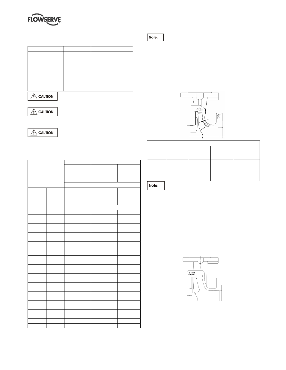
6.7 Setting impeller clearance
This procedure may be required after the pump has
been dismantled or a different clearance is required.
For the CPXV the front impeller clearance setting is as
shown in the table.
Temp.
ºC
(ºF)
CPXV impeller front clearance: mm (in.)
Impellers
up to
210 mm
Impellers
211 mm to
260 mm
Impellers
over
260 mm*
*150CPXV400
*200CPXV400
*150CPXV500
50 (122)
100 (212)
150 (302)
200 (392)
250 (482)
0.3 (0.012)
0.4 (0.016)
0.5 (0.020)
0.6 (0.024)
0.7 (0.028)
0.4 (0.016)
0.5 (0.020)
0.6 (0.024)
0.7 (0.028)
0.8 (0.032)
0.5 (0.020)
0.6 (0.024)
0.7 (0.028)
0.8 (0.032)
0.9 (0.036)
1.0 (0.040)
1.0 (0.044)
1.1 (0.044)
1.2 (0.048)
1.3 (0.052)
For molten salt services above 250 ºC and no
greater than 600
ºC use the value in the above table for
150 ºC noting that the impeller adjustment procedure for
molten salt services cannot be started until pump is at
operating temperature and is only to be done at its
operating tempering temperature. If at any time during
the life of the pump the pumping conditions or operating
temperature changes contact the factory for
reconfirmation calculation of the impeller setting.
For the CPXRV the back impeller clearance is the
setting. Set the back clearance to 2 mm (0.8 in.), as
shown in the following illustration:
a) Before carrying out this procedure on CPXV or
CPXRV ensure that any mechanical seal(s) fitted
can tolerate a change in their axial setting,
otherwise it will be necessary to dismantle the
unit and reset the seal axial position after
adjusting the impeller clearance.