11 clearing a plugged rotor, 12 trailer service tips, 13 removing the rotor – Echo Bear Cat SC5614 User Manual
Page 20: 14 pto lubrication, Warning
5 INCH CHIPPER/SHREDDER
16
SERVICE & MAINTENANCE
BEFORE INSPECTINg OR SERVICINg ANy PART OF THIS MACHINE, SHuT OFF POWER SOuRCE,
DISCONNECT SPARK Plug WIRE FROM SPARK Plug AND MAKE SuRE All MOVINg PARTS HAVE COME TO A COMPlETE STOP.
WaRNING
Remove the discharge door by removing the retaining
1.
bolt securing the discharge door to the chipper
body.
Remove the two 5/16 x 3/4" bolts and nuts securing
2.
the discharge screen to the frame. Pull the bottom
of the discharge screen outward to rotate the screen
off the lip.
Clean any trash or debris out from the screen area.
3.
Place the top lip of the discharge screen into the slot
4.
under the top slope of the chipper body and rotate
the screen so that the bolt holes align with the holes
in the chipper body.
Reinstall the bolts and torque to 17 Ft-lbs.
5.
Replace the discharge door.
6.
Remove the discharge door, discharge screen, belt
1.
guards and rotor shaft end cap.
loosen the bushing bolts holding the drive pulley to
2.
the shaft and remove the pulley.
loosen the set screw in the lock collars. using
3.
a punch and hammer, tap the lock collars in the
opposite direction of normal rotation. Remove the
lock collars.
loosen the set screw in the center of the rotor
4.
assembly.
Remove the two 3/8 x 1/2" bolts running through the
5.
rotor shaft.
using a rubber mallet or other soft hammer, drive the
6.
shaft towards the chipper chute side of the machine.
Once the shaft has been removed, the rotor assembly
7.
can be removed through the discharge opening.
To ease reinstallation, smooth any divots or marks in the
8.
shaft caused by the set screws. Clean the shaft as much
as possible before reinstalling into the machine.
5.11 cLEaRING a pLuGGEd RoToR
5.13 REmovING THE RoToR
The rotor weighs in excess of 100 lbs. It is extremely
important to support the rotor to prevent it from falling
or shifting as the shaft is removed.
WaRNING
Check wheel bolt torque monthly.
1.
Check air pressure in tires monthly.
2.
Check and repack wheel bearings with grease every
3.
12 months.
When towing, always connect the safety chains. Make
4.
sure trailer hitch bolts are tight.
Check trailer lights periodically.
5.
5.12 TRaILER sERvIcE TIps
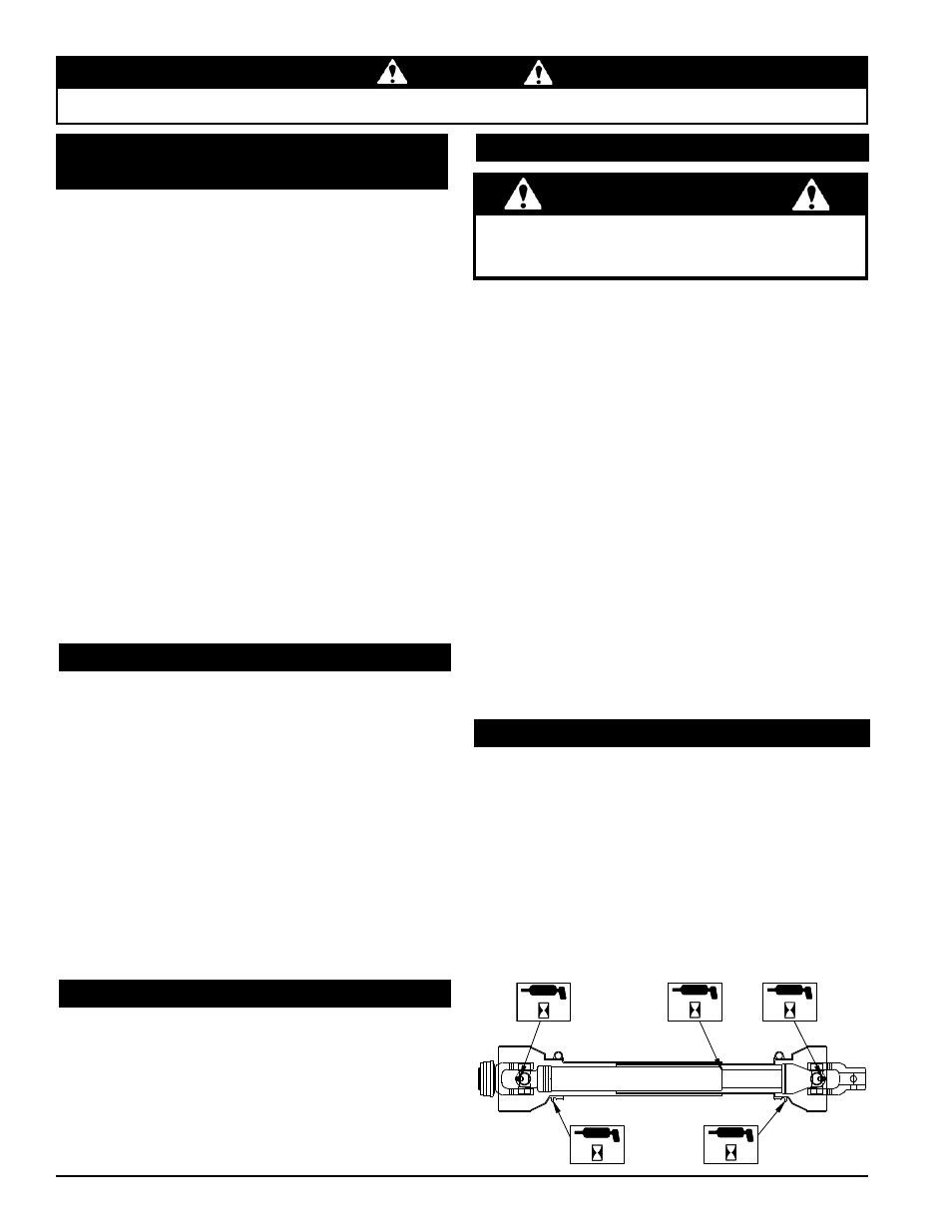
5.14 pTo LubRIcaTIoN
8
h
8
h
8
h
8
h
8
h
Every 8 hours, lubricate PTO cross journals. Make
1.
sure grease purges through all four bearings.
Every 8 hours, lubricate PTO inner tubes. Telescoping
2.
members must have lubrication to operate successfully.
Telescoping members without fittings should be pulled
apart and grease should be added manually with a
brush.
Every 8 hours, lubricate the PTO shield retaining
3.
bearing. Molded nipples on the guard near each guard
bearing are intended as grease fittings and should be
lubricated every 8 hours of operation.
Check the condition of the drive belts annually or every
50 hours of operation, whichever comes first. Replace
the belt if cracked, frayed or worn. To replace the belt,
proceed as follows:
Remove the large belt guard.
1.
Remove the inner belt guide from under the drive belt.
2.
Disconnect and plug the fuel line from the fuel tank.
3.
Remove the fuel tank from the frame assembly.
loosen the four bolts that mount the engine to the
4.
frame and slide the engine back.
Remove the worn belt and install the new belt.
5.
Slide the engine forward until the belt deflection is
6.
7/16" when a 20 lb. load is placed against the belt
(Figure 5.4).
Tighten the engine mount bolts and torque to 30 Ft-lbs.
7.
Replace the fuel tank and reconnect the fuel line.
8.
Install the inner belt guide.
9.
Start the engine to test if the belt is tensioned
10.
correctly.
Replace the large belt guard and resume operation.
11.
5.10 TIGHTENING/REpLacING THE dRIvE
bELT (ToWabLE modELs)