5 installing the blades, 6 removing the discharge screen, 7 setting blade clearance – Echo Bear Cat SC5614 User Manual
Page 18
5 INCH CHIPPER/SHREDDER
14
SERVICE & MAINTENANCE
BEFORE INSPECTINg OR SERVICINg ANy PART OF THIS MACHINE, SHuT OFF POWER SOuRCE,
DISCONNECT SPARK Plug WIRE FROM SPARK Plug AND MAKE SuRE All MOVINg PARTS HAVE COME TO A COMPlETE STOP.
WaRNING
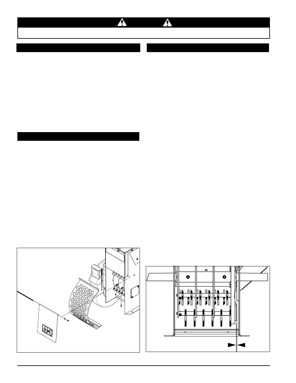
The chipping blades should clear the chipper block, located
inside the frame on the bottom edge of the chipper chute
intake, by 1/16" to 1/8" (Figure 5.2). To adjust the blade
clearance, proceed as follows:
Remove the lower belt guard, discharge door, discharge
1.
screen and the access cover.
loosen the bushing bolts holding the pulley to the rotor
2.
shaft on the front side.
Remove the rotor shaft cover on the rotor shaft rear
3.
side.
loosen the set screws on the lock collars.
4.
use a punch and hammer to tap the lock collars in the
5.
opposite direction of normal rotation so they rotate and
can be removed.
using a rubber mallet, tap the end of the rotor shaft to
6.
obtain 1/16" to 1/8" clearance. The blade clearance
can be viewed through the discharge opening. Rotate
the rotor and check the clearance all chipping blades.
Once clearance has been set, the lock collars must be
7.
replaced to retain the setting. Slip the lock collars over
the hub on the bearings. using a punch and a hammer,
rotate the lock collars in the direction of shaft rotation
and set the lock collars with a hammer tap. tighten
the lock collar set screws.
loosen the bushing holding the belt pulley on the rotor
8.
shaft. Move the pulley on the shaft so it is aligned
directly below the similar pulley on the engine shaft.
The pulley should be moved an equal but opposite
amount the rotor was moved.
Replace the rotor shaft cover, discharge door, discharge
9.
screen and the lower belt guard.
Figure 5.2, Chipper blade and anvil clearance
To REmovE:
Remove the discharge door by removing the pivot rod
1.
securing the discharge door to the chipper body.
Remove the two 5/16 x 3/4" bolts and nuts securing
2.
the discharge screen to the frame. Pull the bottom
of the discharge screen outward to rotate the screen
off the lip.
To INsTaLL:
Place the top lip of the replacement screen onto into
1.
the slot under the top slope of the chipper body and
rotate the screen so that the bolt holes align with the
holes in the chipper body. Reinstall the bolts and
torque to 17 Ft-lbs.
Replace the discharge door.
2.
Place a blade on the rotor and attach with two 5/16 x
1.
1" bolts. Torque to 25 Ft-lb. Repeat for the remaining
blades.
Reinstall the discharge screen by placing the top lip
2.
of the screen into the slot under the top slope of the
chipper body and rotating the screen so that the bolt
holes align with the holes in the chipper body.
Secure using two 5/16 x 3/4" bolts and nuts; torque
3.
to 17 Ft-lbs.
Reinstall the discharge door.
4.
5.5 INsTaLLING THE bLadEs
5.7 sETTING bLadE cLEaRaNcE
5.6 REmovING THE dIscHaRGE scREEN
1/16” - 1/8” GAP
Figure 5.1, Removing the discharge screen