DR Power Walk-Behind 11.50 fpt (August 2010 - Present) User Manual
Page 10
10
DR
®
LEAF AND LAWN VACUUM
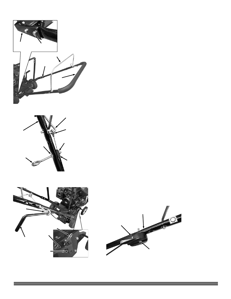
3. Take the Upper Handle Bar Assembly with the Bail on top and slide the flat
ends of the Upper Handle inside the Lower Handle. Secure with four 5/16-
18 x 1" Bolts and four 5/16-18 Nylon Locknuts (Figure 7).
4. Locate the Clutch Cable, which is attached to the LLV machine on the right
hand side. Slip the eyelet end on to the front Bail Bar Hook (Figure 8).
5. Install a Wiz nut onto the Eyebolt threads (flange facing out) and slide the
Eyebolt into the lower hole in the right side of the Upper Handlebar.
Position the Clutch Cable Clamp onto the threads of the Eyebolt and screw a
5/16-18 Nylon Locknut on the end of the Eyebolt until about 3 threads come
through the Nut. Tighten the Wiz Nut on the outside of the Handlebar to
secure the Eyebolt and Clutch Cable to the Handle. Do not over tighten
because the Cable Clamp could become damaged.
NOTE: Tension on the Cable is normal, when installed properly the Bail should be
“spring loaded” and will return to the up or disengaged position. Make sure to keep
the opening of the Eyebolt approximately perpendicular to the angle of the Handles.
6. Slide the shift rod through the eyebolt so that the handle with the rubber grip
is at the top (Figure 9).
7. Insert the lower end of the Shift Rod through the Shift Linkage at the base of
the machine. The Shift Rod is held in place with a Hairspring Cotter Pin,
which gets installed in the hole at the lower end of the Shift Rod behind the
Shift Linkage.
8. Locate the Throttle Control, which is attached to the LLV machine’s Engine
on the left hand side. Install the Throttle Cable to the Handle by inserting a
1/4-20 x 1-3/4" Bolt and 1/4 Washer through the Throttle Control and the
lower hole on the left hand side of the Handlebar (Figure 10). Secure with a
1/4-20 Nylon Locknut.
NOTE: Be careful not to over tighten the Throttle Control Nut. The Bolt also acts
as a pivot point for the Throttle Lever, which must be allowed to pivot freely inside
the plastic housing.
Upper
Handlebar
Figure 7
Bail
Bolts and
Locknuts
Bolts and
Locknuts
Lower
Handlebar
Wiz Nut
Figure 8
Clutch Cable
Clamp
Bail Bar Hook
Clutch Cable
Eyelet
Eye Bolt
Upper
Handlebar
Nylon Locknut
Shift Rod
Handle
Figure 9
Eyebolt
Shift Rod
Shift Linkage
Hairspring
Cotter Pin
Throttle
Control
Figure 10
Upper
Handlebar
Bolt, Washer
and Locknut