Step 6: install the parallel trimming action (pta, Lever, Step 7: attach the acrylic engine shield – DR Power Walk-Behind Pro (2000 - 2001) User Manual
Page 12
DR
®
TRIMMER/MOWER
™
Assembly & Operating Instructions
6
5. Make sure the control cables are over the lower handlebar. Mount the upper handlebar with
the bolt going through the bottom hole. The cup in the outside adjuster should fit snuggly
against the upper handlebar (Figure 9).
6. Add the knob and tighten.
7. Repeat on the other side.
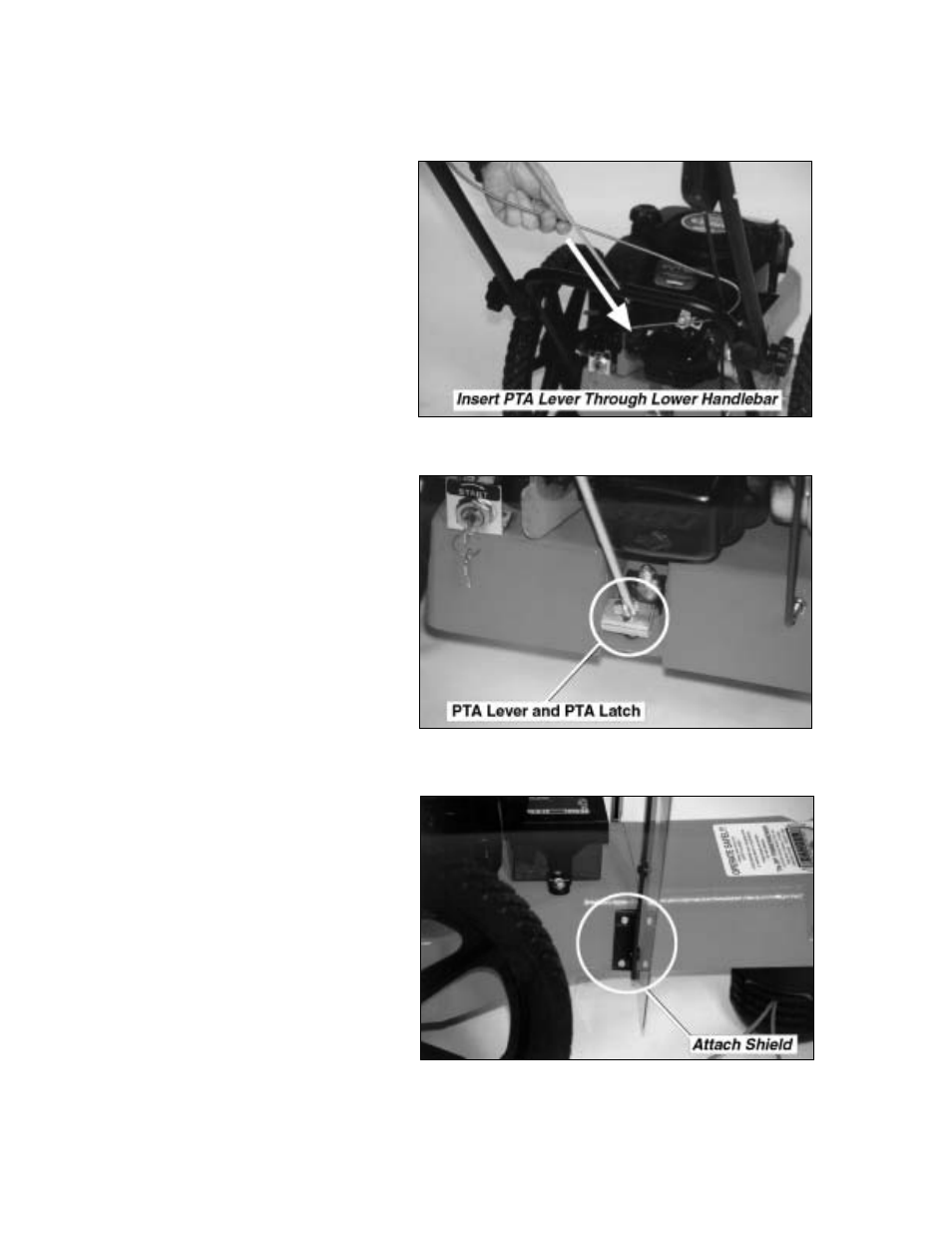
Step 6: Install the Parallel
Trimming Action (PTA
™
) Lever
1. Insert the straight end of the L-shaped
PTA
™
lever through the hole in the
center of the lower handlebar (Figure
10).
2. Align the flat end of the PTA
™
lever
with the corresponding hole in the
PTA
™
latch installed at the center rear
of the frame (Figure 11).
3. Mount a 5/8" long bolt through the two
holes. Tighten with a lock nut until
there is slight resistance, then back off
two full turns.
Note: If the lock nut is too tight, the
PTA
™
lever will be hard to engage.
4. Install the black, vinyl handle grip over
the operator's end of the PTA
™
lever.
Step 7: Attach the Acrylic
Engine Shield
Use the four remaining sets of 5/8" long
bolts and lock nuts to attach the acrylic
engine shield.
You may find it easier to tip the machine
back on its handlebars in order to reach the
underside.
1. Position the shield on the frame in
front of the engine with the bend at the
top facing the handlebars.
2. Insert the bolts from the outside facing
in, screw on the nuts and tighten
(Figure 12).
Figure 10
Figure 11
Figure 12