Connection diagram – DNF Controls ST100 Shuttle Box User Manual
Page 8
8
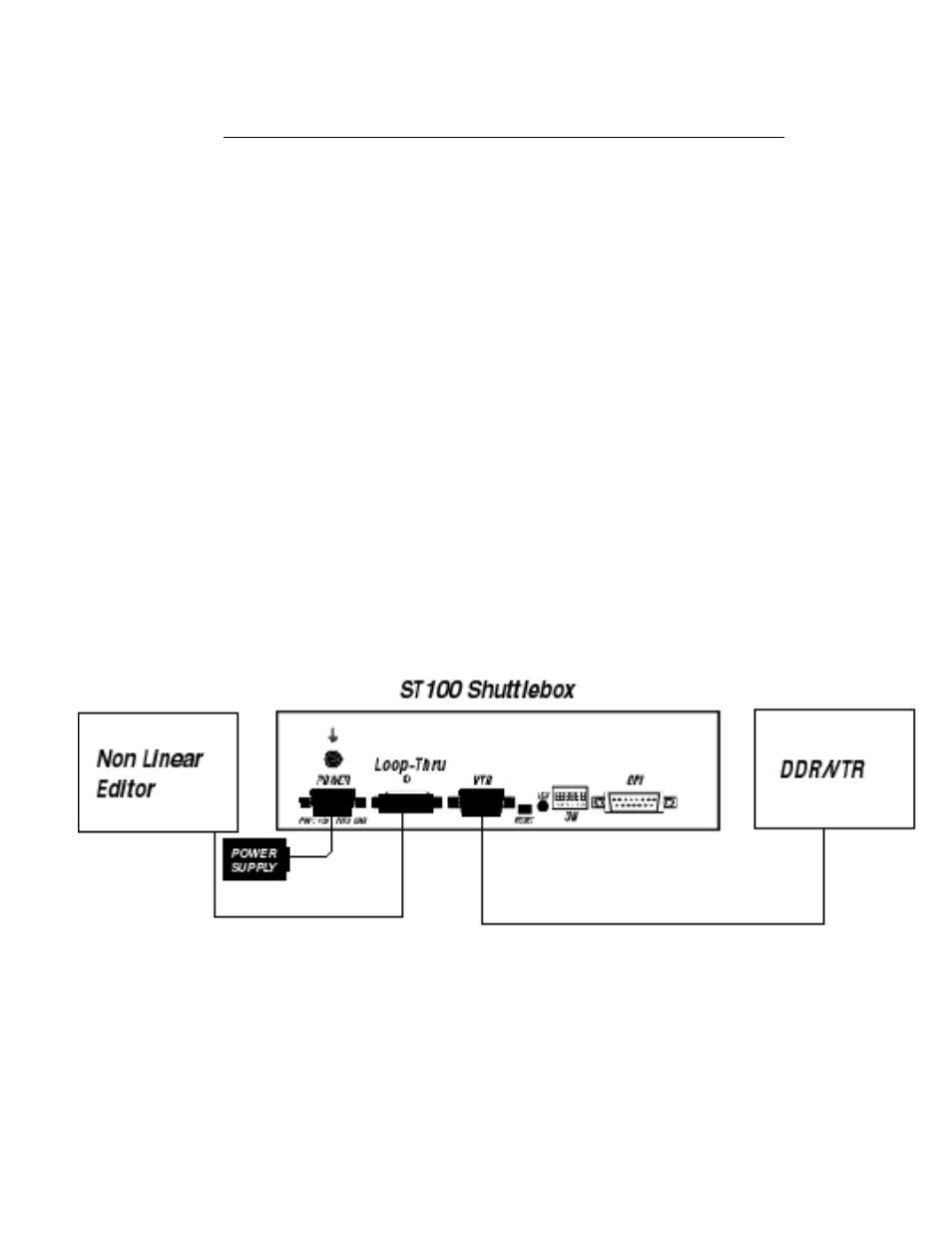
ST100 Shuttle Box
GPI (KEYPAD) INTERFACE CONNECTOR
15-Pin D-Type, Female (DB15-F)
Pin
#
Function Note
1 +9VDC=Table Top; +5VDC=Rack mount
Power for Status Indicators
2 Switch #7, Shift Mode Select
Active Low OC Output
3 Led #1 drive, Record Status Indicator
Active Low OC Output
4
Led #2 drive, Play Status Indicator
Active Low OC Output
5
Led #3 drive, Stop Status Indicator
Active Low OC Output
6
Led #4 drive, Rewind Status Indicator
Active Low OC Output
7
Led #5 drive, Fast Forward Status Indicator
Active Low OC Output
8
Led #6 drive, Jog Mode Indicator
Active Low OC Output
9
Command Common
10
Switch #1, Record Command
Active Low (+5 Pull Up)
11
Switch #2, Play Command
Active Low (+5 Pull Up)
12
Switch #3, Stop Command
Active Low (+5 Pull Up)
13
Switch #4, Rewind Command
Active Low (+5 Pull Up)
14
Switch #5, Fast Forward Command
Active Low (+5 Pull Up)
15
Switch #6, Jog Mode Select
Active Low (+5 Pull Up)
NOTE: There are no internal current limiting resistors for the open collector, status indicator
drives. A 620 ohm resistor in series with the D.C. power supply is recommended for LEDs. Limit
lamp current to 50 ma.
Connection Diagram