DFI SR100-L20C User Manual
Page 20
2
20
Hardware Installation
2. Apply a thin layer of thermal paste on top of the CPU. Do not
spread the paste all over the surface. When you later place the
heat sink on top, the compound will disperse evenly.
3. While holding the retention module base in position (step 1),
place the fan / heat sink assembly on top of the CPU. The 4
screws around the heat sink must match the screw holes of the
retention module base.
Turn each Phillips head screw half way down first to initially stabi-
lize the heat sink onto the board, then finally tighten each screw.
Important:
Do not turn the first screw all the way down followed by
the next and so on. This is to avoid imbalance which might
cause cracks or fractures to the CPU and/or heat sink as-
sembly.
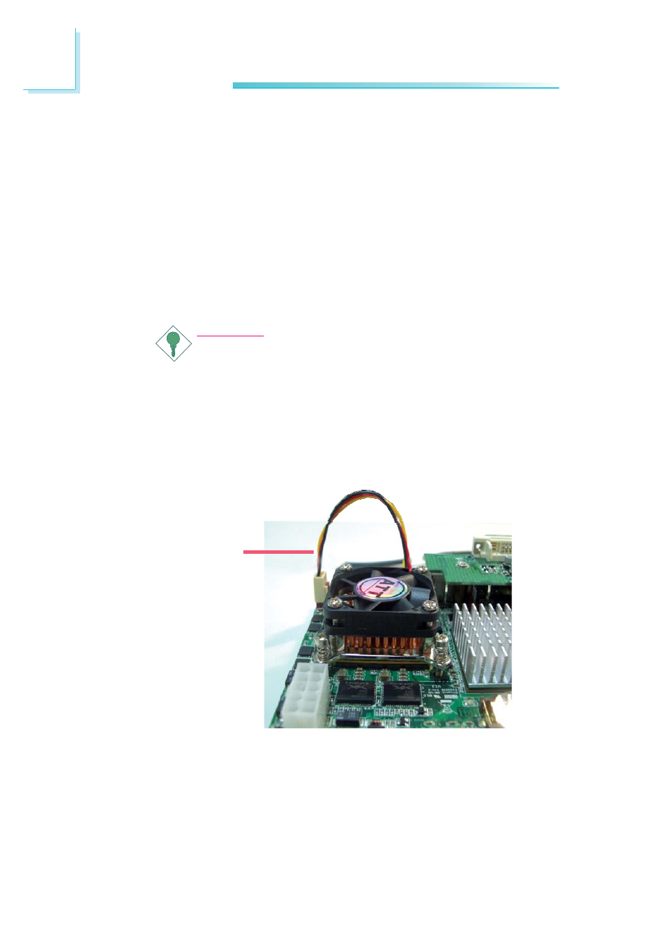
4. Connect the CPU fan’s cable connector to the CPU fan connec-
tor on the system board.
CPU fan
cable
- AR100-DR (112 pages)
- G7B630-N (127 pages)
- G7B630-N (154 pages)
- BT100 (71 pages)
- HR100-CRM (170 pages)
- BT103 (72 pages)
- BT161 (71 pages)
- CM100-C (70 pages)
- CD101-N (69 pages)
- CD102 Series (76 pages)
- CP100-NRM (150 pages)
- CR101-D (67 pages)
- CR100-CRM (177 pages)
- EL339-B (109 pages)
- G5C100-NR (160 pages)
- HD100-H81 (79 pages)
- HD101-H81 (83 pages)
- HD173-H81 (70 pages)
- HM100-QM87 (97 pages)
- HM103-QM87 (99 pages)
- HU103 (95 pages)
- KB161 (68 pages)
- HU173 (90 pages)
- LR100-N18M/N18S (126 pages)
- LR102-B18M (138 pages)
- EL630-NR (149 pages)
- NP101-D16C (150 pages)
- SB102-D (60 pages)
- NP102-N16C (144 pages)
- MB630-CRM (171 pages)
- SB630-CRM (184 pages)
- SB630-CRM (183 pages)
- SR100-N (152 pages)
- LT600-L (149 pages)
- G7B630-N (147 pages)
- CA331-P (131 pages)
- EL330-DR (142 pages)
- CP337-NRM (174 pages)
- HD310-Q87 (101 pages)
- EL620-C (192 pages)
- G7L630-B (133 pages)
- HD330-H81 (81 pages)
- HD330-Q87 (85 pages)
- HD332-H81 (76 pages)