Chapter 2 – DFI CD102 Series User Manual
Page 12
www.dfi .com
12
Chapter 2 Hardware Installation
Chapter 2
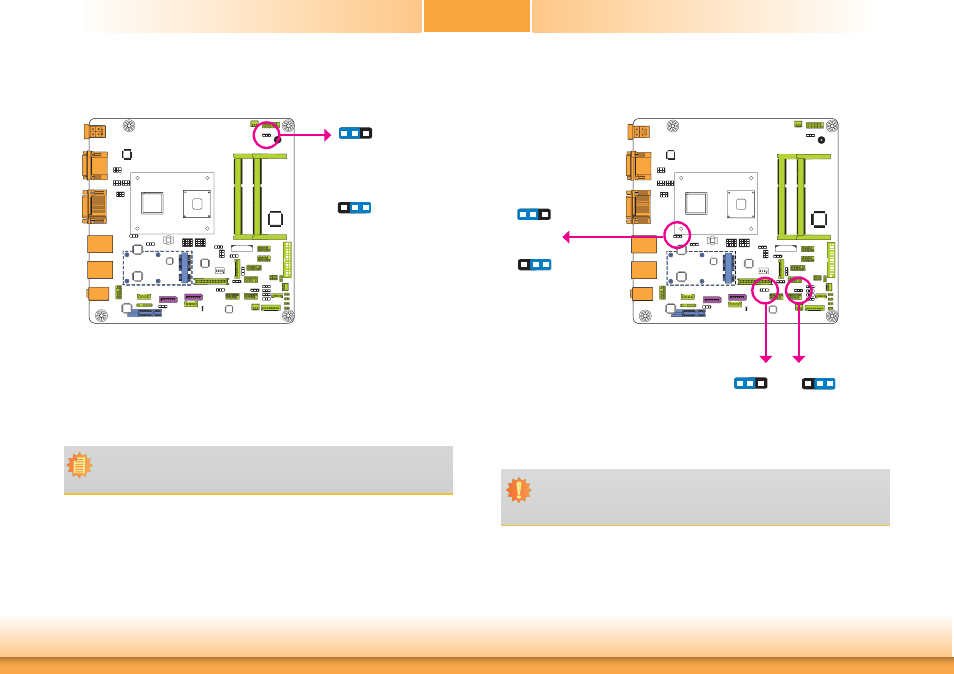
Auto Power-on Select
1-2 On:
Power-on via power button
(default)
2-3 On:
Power-on via AC power
3
1 2
3
1 2
JP19 is used to select the method of powering on the system. If you want the system to
power-on whenever AC power comes in, set JP19 pins 2 and 3 to On. If you want to use the
power button, set pins 1 and 2 to On.
When using JP19 “Power On” feature to power the system back on after a power failure
occurs, the system may not power on if the power lost is resumed within 5 seconds (power
flicker).
Note:
In order to ensure that power is resumed after a power failure that re covers within
a 5 second period, JP19 must be set to pins 2-3 and the “Power Failure Control” in
CMOS is set to “Always On”.
JP5, JP14 and JP21 are used to select the power of the USB ports. Selecting +5V_standby will
allow you to use a USB device to wake up the system.
USB Power Select
USB 0-1/2-3
(JP5)
1
3
2
1
3
2
USB 6-7
(JP14)
2-3 On:
+5V_standby
1-2 On: +5V
(default)
2-3 On:
+5V_standby
1-2 On: +5V
(default)
Important:
If you are using the Wake-On-USB Keyboard/Mouse function for 2 USB ports, the
+5V_standby power source of your power supply must support ≥1.5A. For 3 or more
USB ports, the +5V_standby power source of your power supply must support ≥2A.
1
3
2
1
3
2
JP19
USB 4-5
(JP21)