Installation, Model 4pk-scs page 8, Master and switched ports – Dataprobe 4PK-SCS User Manual
Page 8: Pin# designation, Rts / dtr selection, Ground / common pole
Model 4PK-SCS
Page 8
INSTALLATION
Master and Switched Ports
Connection to the Switched A-D ports is made
using 25 pin D Subminiature connectors on the
rear of the unit. The following leads are supported
for Asynchronous communications:
Pin# Designation
2
Transmit Data
3
Receive Data
4
Request to Send
5
Clear to Send
6
Data Set Ready
7
Signal Ground
8
Data Carrier Detect
20
Data Terminal Ready
The four switched ports A-D are wired DCE (output
data on pin 3,RD). The Master port is wired for as DTE.
To directly connect a terminal device to the Master
Port, a Null cable is required. Refer to Figure 3.
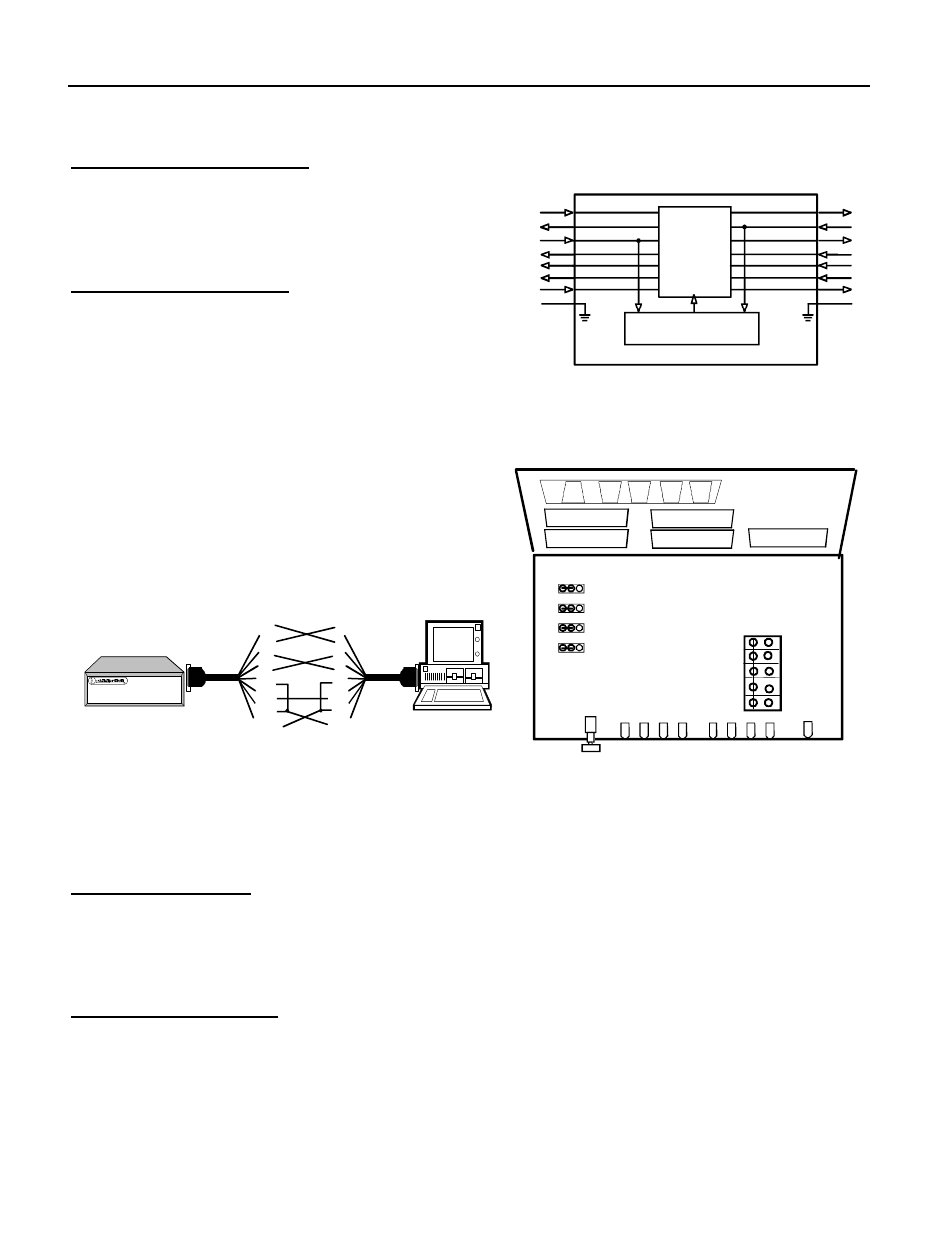
RTS / DTR Selection
Jumpers JP1 through JP4 allows selection of RTS (default) or DTR as the control lead used for Lead
Control. To access these jumpers, disconnect the power source and remove the top cover of the
4PK-SCS by loosening the two screws on the underside of the unit. The jumpers are located behind
the B and D Port Connectors. See Figure 4.
Ground / Common Pole
Any or All of the relay commons can be connected together and/or connected to board ground using
the header J9, located adjacent to the power LED. ( Used in conjunction with the 9 pin relay out )
Typical
Port A-D
RTS
Mon.
Switch
Control
Code
Mon.
Electronic
4 Way
Switch
2 TD
3 RD
4 RTS
5 CTS
6 DSR
8 DCD
DTR
20
7 SG
2 TD
3 RD
4 RTS
5 CTS
6 DSR
8 DCD
DTR
20
7 SG
Master
Port
Figure 2
System Diagram
4
3
2
1
C
B
D
MASTER
A
B
C
D
POWER
A
Port
Select
PORT
D
C
B
A
Port Status
Relay Status
Relay Connections
RTS
DTR
4
3
2
1
Board GND
K4 Common
K3 Common
K2 Common
K1 Common
Figure 4
Component Location
(Not to Scale)
2
3
4
5
6
7
8
20
Null Connection to Terminal
Control Leads Required vary from device to
device. Consult your operations manual for
details on your specific needs.
2
3
4
5
6
7
8
20
4P-MAS
Master Port
Figure 3
Null Modem Connection