Dataprobe iBoot-DC Quick Start User Manual
Quick start guide, What’s included, Available online at
IBoot-DC quick start
© 2011 Dataprobe Inc.
V120423E
What’s Included
•
iBoot-DC Unit
•
Network Cable
•
This Quick Start Guide
Available Online at
dataprobe.com/support/iboot
•
Complete Product Manual
•
Device Management Utility
•
Latest iBoot Firmware
•
Software Developer Tools
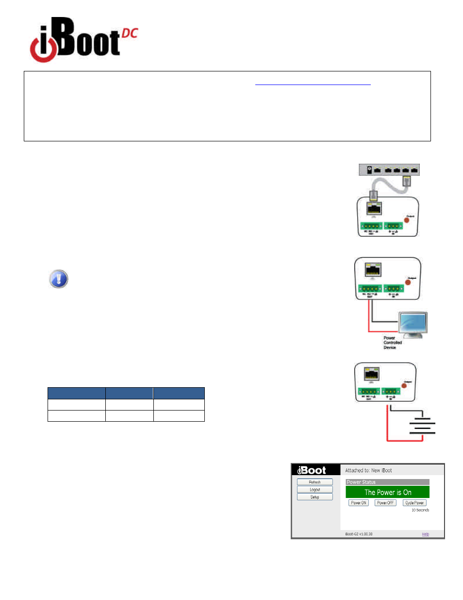
Connections
1.
Connect Network.
iBoot-DC
supports 10/100 Ethernet using the cable supplied, or other
suitable unshielded twisted pair (Cat 5) cabling. When power is connected to the iBoot-DC, the
Link (amber) and Activity (green) LEDs on the network connector indicate when the network
connection is properly established.
2.
Connect Powered Device.
Connect the device to be powered ON and OFF to the screw
terminals marked OUT. Connect the positive lead to the + and the negative (ground) to the - .
The Positive is switched. The standard connection is to the NO terminal. Screw terminal
assemblies are removable for easier connections. With the positive connected to the NO
terminal the power will be ON when the iBoot-DC displays ON. If the device has a power
switch, turn it on, to allow iBoot-DC to control the power.
Make sure that the load does not exceed 5 Amps for 5 - 29.9 VDC or
2 Amps for 30 - 48 VDC.
3. Connect Power
Connect the DC power source to the terminals marked IN. Connect the
positive lead to the + and the negative (ground) to the - . The iBoot-DC is default power On.
The screw terminal assembly is removable for easier connection. The LED marked Output is
on when the power is connected to the NC terminal.
Web Browser Access
Factory Default IP Address: 192.168.1.254
Factory Default Security Credentials:
Role
Username
Password
Administrator
admin
admin
User
user
user
To access the iBoot from the default IP Address, requires the PC to be on the same local
network (IP Address 192.168.1.nnn). If it is not, change the iBoot IP
Address using one of the methods on the following page.
After pointing the browser to the IP Address of the iBoot, enter the
Administrator Username and Password to access the complete setup
features. Enter the User credentials to access only the power control.
Once the user is validated, the Control and Status is displayed.
To control the power, click on the appropriate button. During power
cycling, the Power Status bar will indicate the temporary status, with a
blue background. Once the cycle is complete, the status bar will
revert to its original condition.
Quick Start Guide
Fig.1 Connect Network
Fig. 2 Connect Device
Fig. 3 Connect Power
Fig. 4 Status and Control Page