Daktronics AB-1600-1.5,2.5 User Manual
Page 34
3-12
Electrical Installation
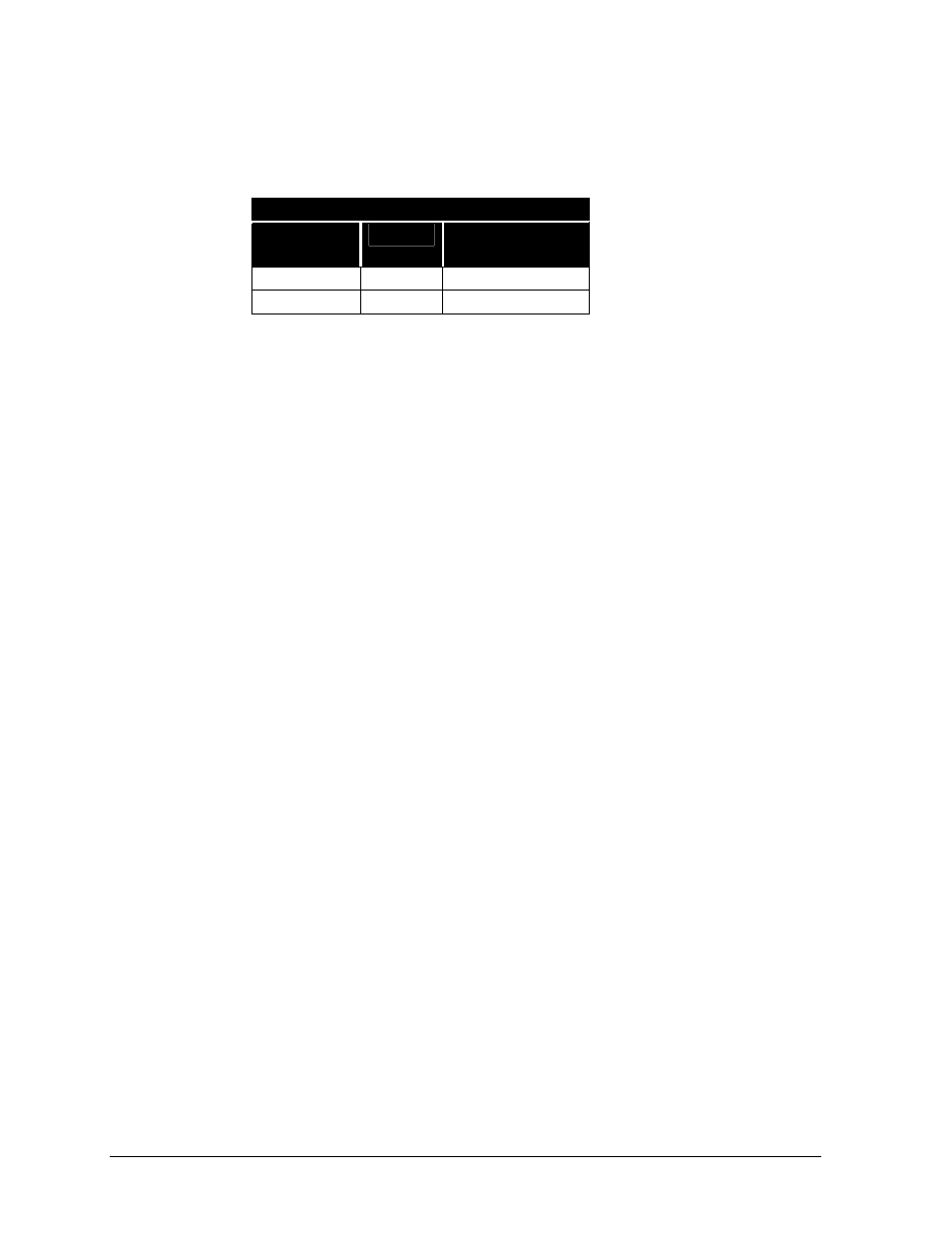
3. Use the table within this sub-section titled “Venus 1500 Fiber Optic Connection” to connect
fiber optic cable at the signal converter and the Venus 1500 controller fiber optic board.
•
The Venus 1500 fiber optic board mounts on the Venus 1500 controller board within the
Venus 1500 enclosure. Refer to Drawings A-103727 and A-148878.
•
The fiber optic connectors on the side of the signal converter are clearly labeled.
Venus 1500 Fiber Optic Signal Connection
Signal
Converter
Cabling
Venus 1500
Fiber Board
RX-Out (J3)
-----
TX-In (J4)
TX-Out (J2)
-----
RX-In (J5)
4. The controller computer connects to the nine-position connector (DB9) on the signal converter
labeled “J1.” Refer to Drawing A-148878 found at the end of this section.
Refer to Light Detector Installation - Venus 1500 Systems in Section 3.8 for instructions on
installing the light detector for this display. If ordering a temperature sensor, refer to Section 3.9
for temp sensor installation instructions.
If this display is one face of a two-face, 2V cabinet display configuration, refer to Section 3.7 for
instructions on running signal from the master to the echo unit.
Venus 4600 System Using Fiber Optic Signal
Venus 4600 fiber optic systems use a two-fiber cable to transmit data from an A/B interface in the
control room to the serial line interface within the display. The cable is Daktronics part number
W-1242. Keep the following in mind when working with W-1242 cable.
•
Do not subject W-1242 cable to mechanical flexing after installation.
•
It is suitable for direct burial or routing in conduit.
•
It has a maximum length of 1,500 feet.
Complete the following steps to connect signal to a Venus 4600 system using fiber optic cable.
1. Route conduit (if needed) and W-1242 cable from the control room to the knockouts on the
right side (rear view) of the display – or master display if installing a 2V configuration.
2. Pull fiber optic cable to the bottom of the serial line interface board.
3. Connect fiber cable to J8, fiber optic input, on the serial line interface board and to J8 (RX) on
the A/B interface. Refer to Drawings A-107196 and A-103740.
4. The controller computer connects to the 15-position connector (DB15) on the A/B interface.
Refer to Drawing A-107196.
If the optional photo/temp sensor was ordered with this display refer to Optional Photo/Temp
Sensor Installation - Venus 4600 Systems in Section 3.8.
If this display is one face of a two-face, 2V cabinet display configuration, refer to Section 3.7 for
instructions on running signal from the master to the echo unit.
If this display does not have a photo/temp sensor and is not one face of a two-face, 2V cabinet
configuration, refer to Section 3.10.
If this display is one face of a two-face, 2V cabinet display configuration, refer to Section 3.7 for
instructions on running signal from the master to the echo unit.