Section 8: parts replacement, 1 about replacement parts, Section 8 – Daktronics AF-3700-20 RGB User Manual
Page 45: Parts replacement, About replacement parts, Figure 47: interior location of components, Figure 48: typical label
Section 8: Parts Replacement
This section covers the replacement of parts in a GalaxyPro display. The first section provides a list of
parts and their Daktronics part numbers. The second section gives instructions for replacing the most
basic parts. For information on obtaining replacement parts from Daktronics, refer to Section 9.
Disconnect power when servicing the display.
Qualified service personnel are recommended for servicing internal electronic components.
8.1 About Replacement Parts
Daktronics AF-3700 GalaxyPro
®
displays are designed and manufactured for performance,
reliability, easy maintenance, and long life. However, on occasion, parts may need to be
replaced. Section 9 provides information on obtaining replacement parts from Daktronics.
Appendix B provides information about the connectors referenced in the replacement
instructions.
This section provides replacement instructions for the following parts:
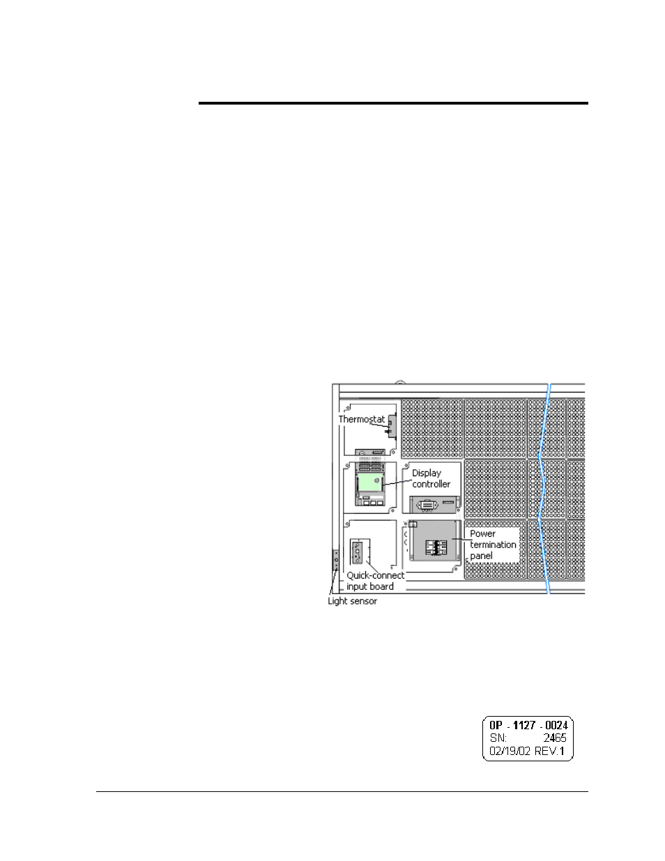
Figure 47: Interior Location of Components
• modules
• controller
• power supplies
• light sensor
• temperature sensor
These components are generally
located as shown in Figure 47. Note
that sectional displays (those 112 and
128 pixels high) contain a power
termination panel and thermostat in
each section. Also, larger displays
will contain more than one signal
connection between primary and
mirror displays. Check the Layout
Drawing in Appendix A for the
specific display size to find the exact
location of components.
The following table contains some of the items that may need to be replaced in a display over
a period of time. If a circuit board or assembly is not listed in the Replacement Parts List, use
the label to order a replacement. Most circuit boards and components within this display
carry a label that lists the part number of the unit. A typical label is shown in Figure 48 with
the part number in bold.
Figure 48: Typical Label
Cables will not carry a part number label. To assist with correct
identification of cables and connectors, refer to the descriptions in
Appendix B.
Parts Replacement
35