2 temperature sensor diagnostic, Temperature sensor diagnostic, Figure 44: controller diagnostics – Daktronics AF-3700-20 RGB User Manual
Page 40: Figure 45: temperature sensor board
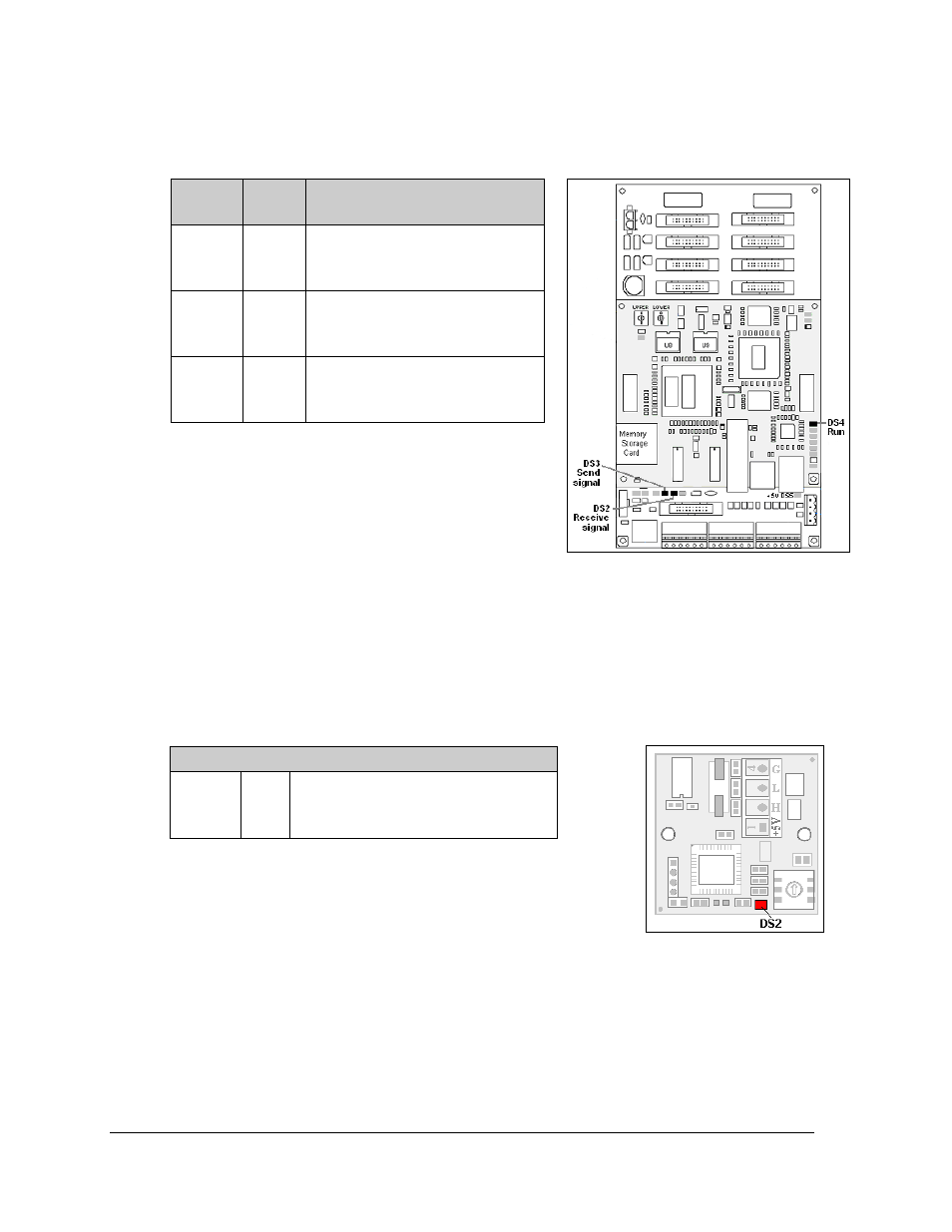
A GalaxyPro controller is illustrated in Figure 44 with essential diagnostic LEDs labeled. The
table explains the information that each of these LEDs provides.
Diagnostics and Troubleshooting
30
7.2 Temperature Sensor Diagnostic
If the display includes a temperature sensor, the temperature sensor board will also provide
diagnostic information. The temperature sensor board is located inside the temperature
sensor housing which is located near the display (Figure 45). The sensor board diagram
below shows the red diagnostic LED (DS2) near the bottom edge of the component.
Refer to Appendix C for temperature sensor mounting and
connections.
Figure
label
LED #
Operation
Run
DS4
Steady FLASH about once per
second indicates controller is
working properly.
Send
signal
DS3
OFF is the normal state. FLASH
when transmitting communication
from the computer.
Receive
signal
DS2
OFF is the normal state. FLASH
when receiving communication
from the computer.
Figure 44: Controller Diagnostics
Figure 45: Temperature sensor
board
Temperature Sensor
DS2
Run
FLASH at variable rates when sending
temperature information; evidence that
the unit has power.