Prolink router (plr), Self test, 2 p rol ink r outer (p l r ) – Daktronics 4000 Series Digital Billboard User Manual
Page 22
16
R eplacing Dis play C omponents
Figure 22: PLR Enclosure
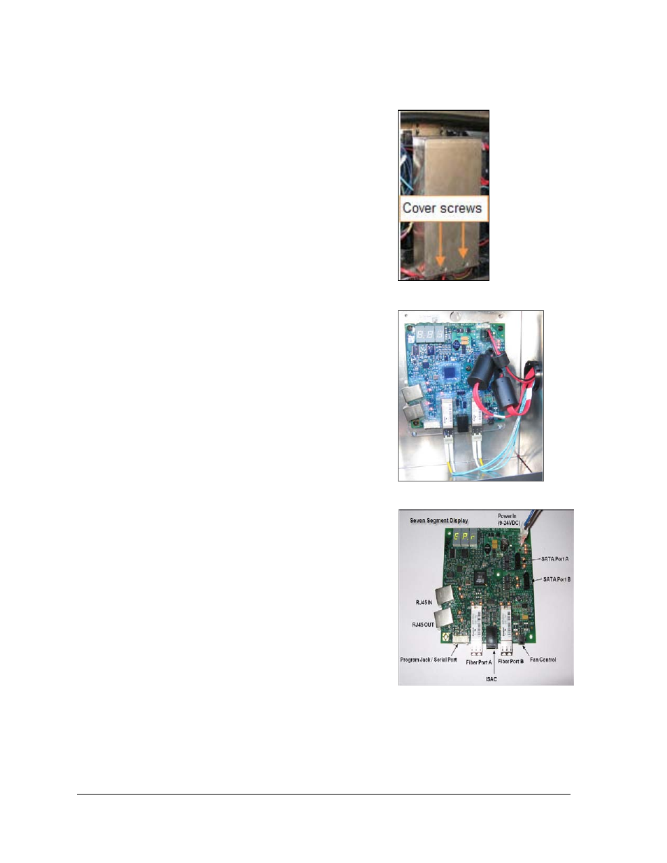
Figure 23: PLR
Figure 24: PLR Components
4.2 P roL ink R outer (P L R )
Required tools: Phillips screwdriver
Refer to Figure 24 for an example of the PLR.
1. Access the interior of the display. Refer to
Section 3.2.
2. With a Phillips screwdriver, loosen the two
screws on the PLR enclosure cover.
3. Slide the cover to the right to remove the PLR
enclosure cover.
4. Disconnect all power and signal cables from
the PLR. Refer to Figure 25.
5. Use a Phillips screwdriver to remove the old
PLR from the PLR enclosure.
6. Install the new PLR.
7. Connect the cables to the new PLR. Verify the
cables are properly seated.
8. Reinstall the PLR enclosure cover.
S elf Tes t
1. Connect a duplex fiber cable to Fiber Ports A and
B. Refer to Figure 26 and Figure 27.
2. Connect a SATA cable to SATA ports A and B.
3. Connect the power cable to the PLR to start the
self-test.
This test may take up to 90 seconds to complete.
When the PLR has successfully sent and received data
through each of the connected ports, the letters
“P.A.S.” will appear on the seven-segment display.
•
If the PLR detects a problem, the letters
“E.r.r.” will appear on the seven-segment
display and then it will show the two ports
that it detected the problem from (e.g. F01,
F02 for the fiber ports or F05, F06 for the
SATA ports).