Section 4: replacing display components, 1 photocell, Test – Daktronics 4000 Series Digital Billboard User Manual
Page 21: Section 4, Replacing display components, Photocell, S ection 4: r eplacing dis play c omponents, 1 p hotocell
R eplacing Dis play C omponents
15
S ection 4: R eplacing Dis play C omponents
This section provides information on removing and replacing display components.
4.1 P hotocell
Required tools: Wrench, utility knife, cable ties
A 25' cable is attached to the replacement photocell.
1. Unplug the old photocell cable from the remote
enclosure.
2. Cut any cable ties that hold the photocell cable in
place along the back of the display.
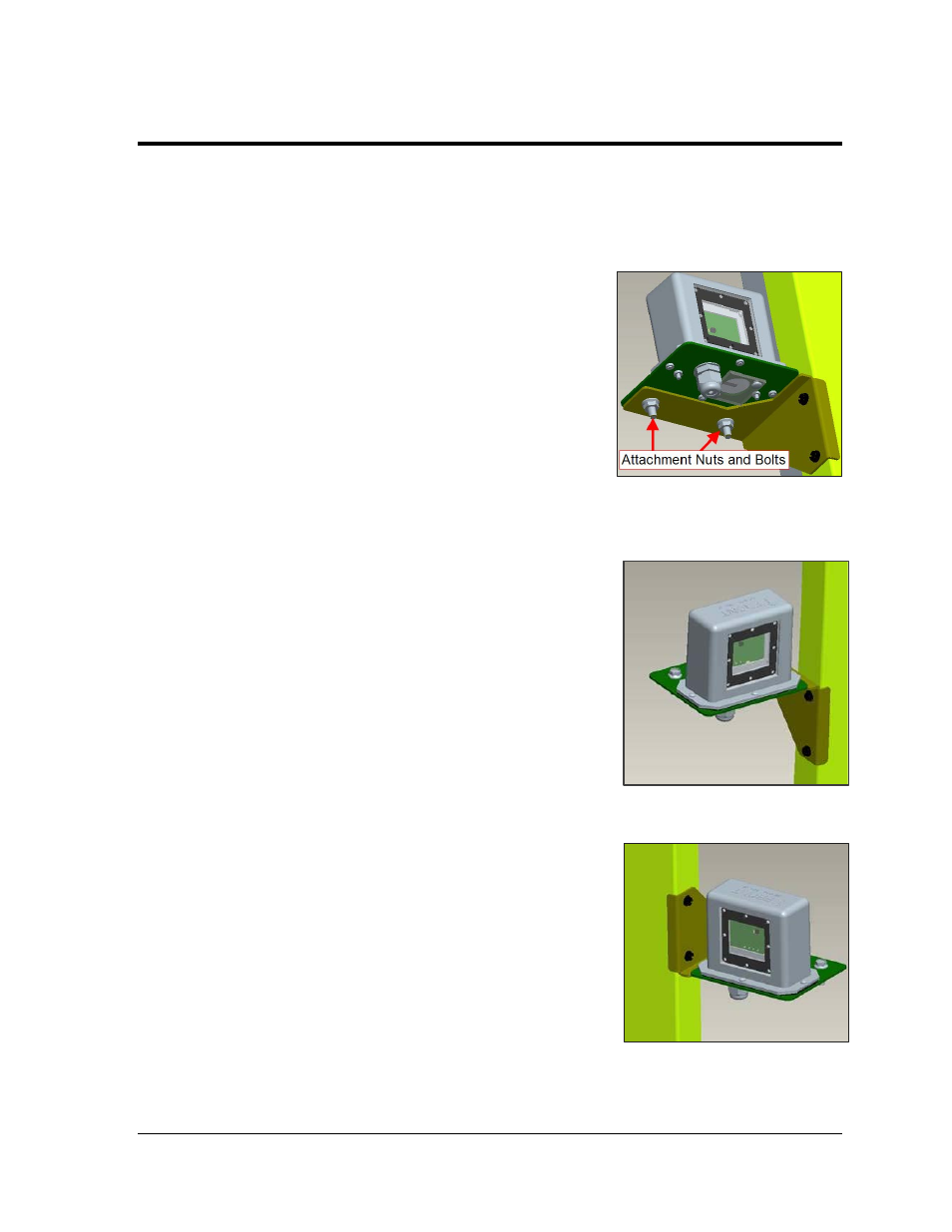
3. Use a wrench to remove the two attachment nuts
and bolts that hold the old photocell to the
mounting bracket. Refer to Figure 21.
4. Use the two attachment nuts and bolts to install the
new photocell in place of the old photocell. Refer to
Figure 20 and Figure 21 for mounting method
reference. Ensure the arrow on top of the photocell
is pointing the same direction as the display face.
Note: The photocell must be installed right side up
on the mounting bracket. If installed upside down
or sideways, the ambient light readings will be
inaccurate, thus causing display brightness to be
inaccurate.
5. Route the 25' cable from the photocell assembly to
the connection in the remote enclosure. If needed,
attach the extension cable (located in the spare
parts box).
6. Using cable ties, attach the photocell cable to the
cable tie anchor points along the back of the
display.
Tes t
1. Test the photocell by covering all sensor windows
(front, back, and bottom) with a heavy piece of fabric to
dim the display. It may take a minute or two for the
display to dim.
Figure 19: Attachment Nuts and Bolts
Figure 20: Left Side Mounting
Figure 21: Right Side Mounting