Section 1: overview of the displays, 1 display details, Section 1 – Daktronics Galaxy AF-3500/3550 User Manual
Page 5: Overview of the displays, Display details
Overview of the Displays
1
Section 1: Overview of the Displays
Note: This manual provides installation, maintenance, and troubleshooting information to help ensure the optimal
performance of Daktronics Galaxy
®
AF-35XX displays. Diagnostic information and parts replacement are also
“Glossary” is found near the end of this manual.
1.1 Display Details
The Galaxy
®
model numbers are described as follows:
Displays are either single-face or 2V (Two View) units. In 2V units, the first display is referred to as primary.
The second display is called the mirror.
A typical display system is controlled with a Windows
®
-based computer running Venus
®
1500 software.
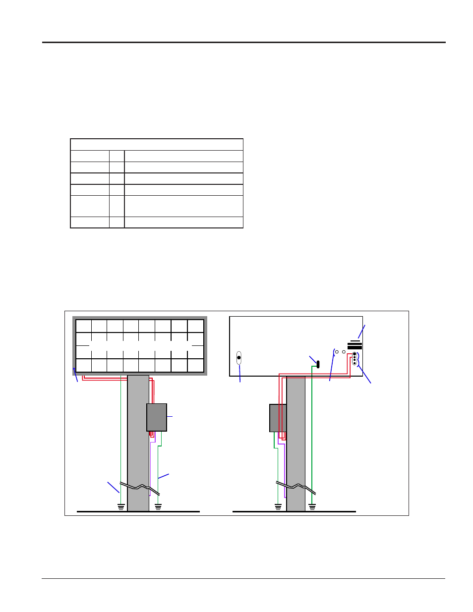
Figure 1 shows front and back views of a typical display.
AF-35XX-RRxCCC-MM-R,A,RGB-XX
AF-35XX
=
Outdoor Galaxy display
RR
=
Number of pixel rows high
CCC
=
Number of pixel columns long
MM
=
Pixel pitch in millimeters
R, A, RGB =
LED Color: R (Red), A (Amber),
RGB (Full Color – Red, Green, Blue)
XX
=
SF (Primary) or 2V (Primary/Mirror)
Primary Display – Front View
Primary Display – Rear View
Ground Lug
Connect
Label(s)
Quick
Connect
Inputs
Output
to Mirror
Display
Signal
Termination
Enclosure
Signal Enclosure
Ground Electrode
Conductor
(When Required)
Grounding
Electrode
Conductor
Blue Dot
Optional
Conduit
Drilling
Guides
(Etched)
Figure 1: Display Components