Section 4: signal installation overview, 1 primary/mirror display interconnections, 2 usb to ethernet adapter – Daktronics Galaxy AF-3500/3550 User Manual
Page 15: 3 setting the ip address on the display controller, Section 4, Signal installation overview, Primary/mirror display interconnections, Usb to ethernet adapter, Setting the ip address on the display controller
Signal Installation Overview
11
Section 4: Signal Installation Overview
For specific details on installing the communications, consult the quick guide and manual included with the
communication equipment. Each type of communication is listed below with its manual number.
Note: These are the standard communication types but each site is unique and may include additional equipment. If
problems arise, contact the display’s service company or Daktronics Customer Service.
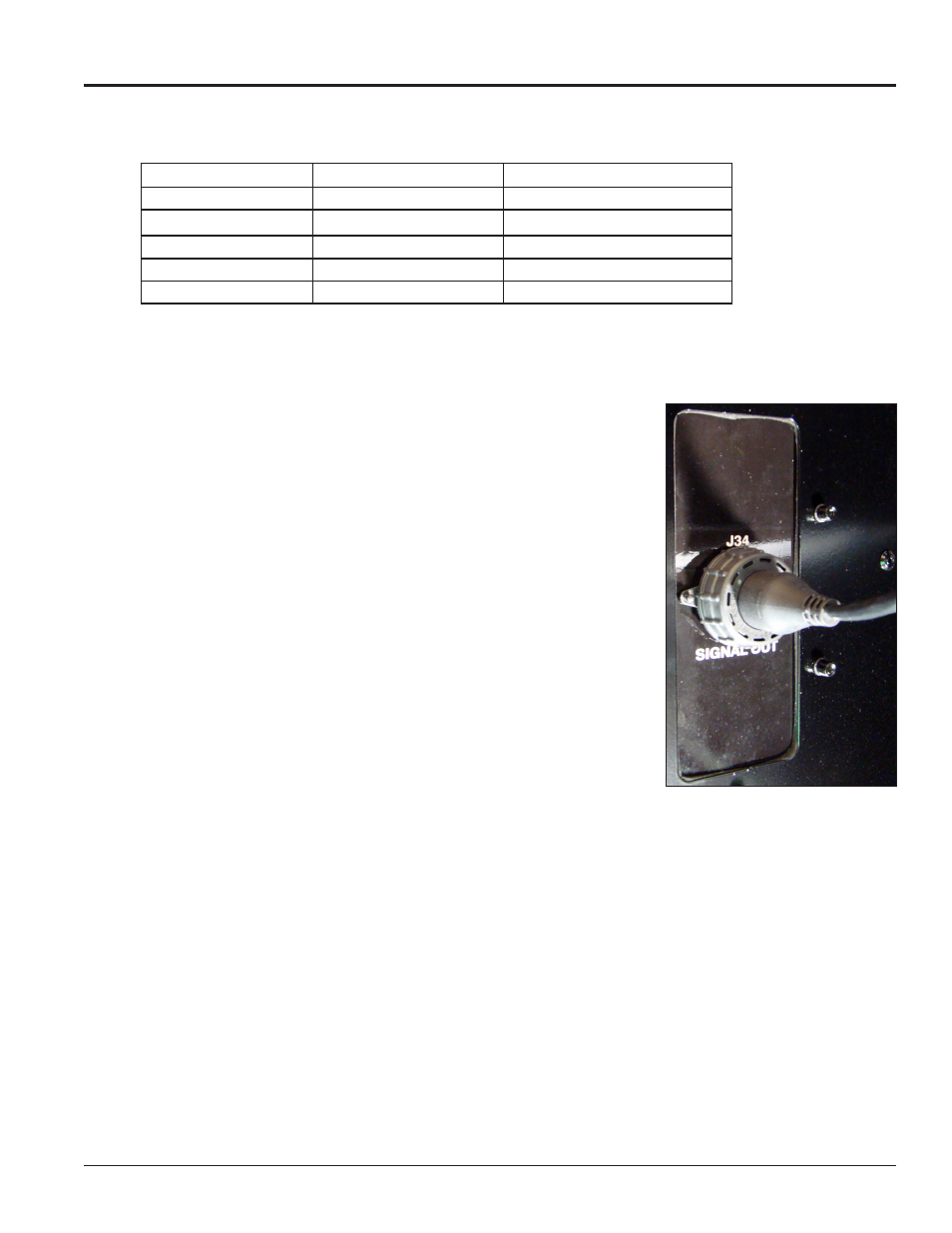
4.1 Primary/Mirror Display Interconnections
If this display is a two-sided primary/mirror display, a quick-connect cable
is provided to connect the signal between the two faces. Refer to
for an example. Secure the excess cable to the support structure to prevent
damage from weather or vandalism.
4.2 USB to Ethernet Adapter
A USB to Ethernet adapter is included with the display and can be used
to bypass network configuration in situations where simple point-to-point
communication is required. The adapter creates a secondary network that
is dedicated to communication with the display, but network operation is
still enabled through the primary network.
The USB to Ethernet Adapter can be used in conjunction with
communication kits supplied with the display. Refer to
for
more information regarding the adapter.
4.3 Setting the IP Address on the Display Controller
Galaxy AF-35XX display controllers are set to the default IP address
172.16.192.25 prior to shipping. This address can be changed to an address specific to the local display
network. Obtain an appropriate IP address for the display from the network administrator.
The display must have power and M2Config installed on the computer to complete the following steps.
Communication with the display controller is necessary and can be done through the purchased
communication method or directly to the display controller using a Cat5 cable.
Display power must be On to complete this configuration.
1. Set the computer’s IP address to 172.16.192.20 and the Subnet Mask to 255.255.0.0.
2. Open M2Config:
Communication Type Communication Manual Communication Quick Guide
Wireless Ethernet Bridge
Ethernet
Fiber Ethernet
WiFi
USB to Ethernet Adapter N/A
Figure 9: Primary/Mirror Quick-
connect Cable