Section 7: diagnostics and troubleshooting, 1 controller diagnostics, 2 mlc diagnostics – Daktronics Galaxy AF-3500/3550 User Manual
Page 25: Section 7, Diagnostics and troubleshooting, Controller diagnostics, Mlc diagnostics, Diagnostic leds
Diagnostics and Troubleshooting
21
Section 7: Diagnostics and Troubleshooting
Important Notes: Disconnect power when servicing the display. Only qualified service personnel should service
internal electronic components.
7.1 Controller Diagnostics
The controller is the “brains” of the display, receiving
communication from the computer and then sending
information to the modules. The controller is located in
the lower-left area of displays as shown in
Figure 10.
LEDs on the controller show whether power and
communication signals are working properly.
Mirror displays do not contain a controller. Instead,
they have an MLC or repeater card which helps relay
information from the primary controller.
To access the interior of the display, refer to
Section
6.2 for instructions and illustrations. Remember to
disconnect power to the display before accessing the
interior. However, once the modules are removed and
wires are found to be safe, power can be turned back on
to view the diagnostic LEDs.
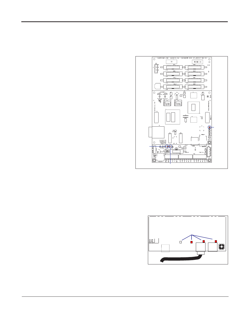
A Galaxy controller is illustrated in
Figure 18 with
essential diagnostic LEDs labeled:
• The DS4 LED signifies the controller’s
operational status. This LED flashes about
once per second to indicate the controller is
functioning properly.
• The DS3 LED signals the controller’s transmission status. This LED flashes only when transmitting
information to the modules.
• The DS2 LED displays the controller’s receiving status. This LED flashes only when receiving
information from the control computer.
7.2 MLC Diagnostics
The Multi-Line Controller (MLC) unit contains four red
diagnostic LEDs. When properly connected to the primary
display, the LED labeled DS25 is off and the other LEDs are on,
as shown in
DS4 Run
DS2 Receive
DS3
Transmit
Figure 18: Controller Diagnostics
MLC
J25
J21
J22
DS23
DS24
DS25
DS27
REPEA
T IN
REPEA
T OUT
▼
▼
▼
▼
Diagnostic LEDs
Figure 19: MLC Diagnostic LEDs