For displays with internal power termination, 7 power routing in the display, Power routing in the display – Daktronics Galaxy AF-3500/3550 User Manual
Page 12: 8power installation
8
Power Installation
For Displays With Internal Power Termination
Terminating single-phase power to the internal power
termination panel:
1. Open the display as explained in Section 6 and locate
the power termination panel.
2. Route the cable through conduit to the back of the
display. Use the
3
/
4
” knockout for access, being
careful not to damage internal components.
3. Connect the neutral wire to the neutral lug and the
live wires to the Line 1 and Line 2 lugs.
4. The ground wire connects to the grounding bus bar.
Figure 7 for an example.
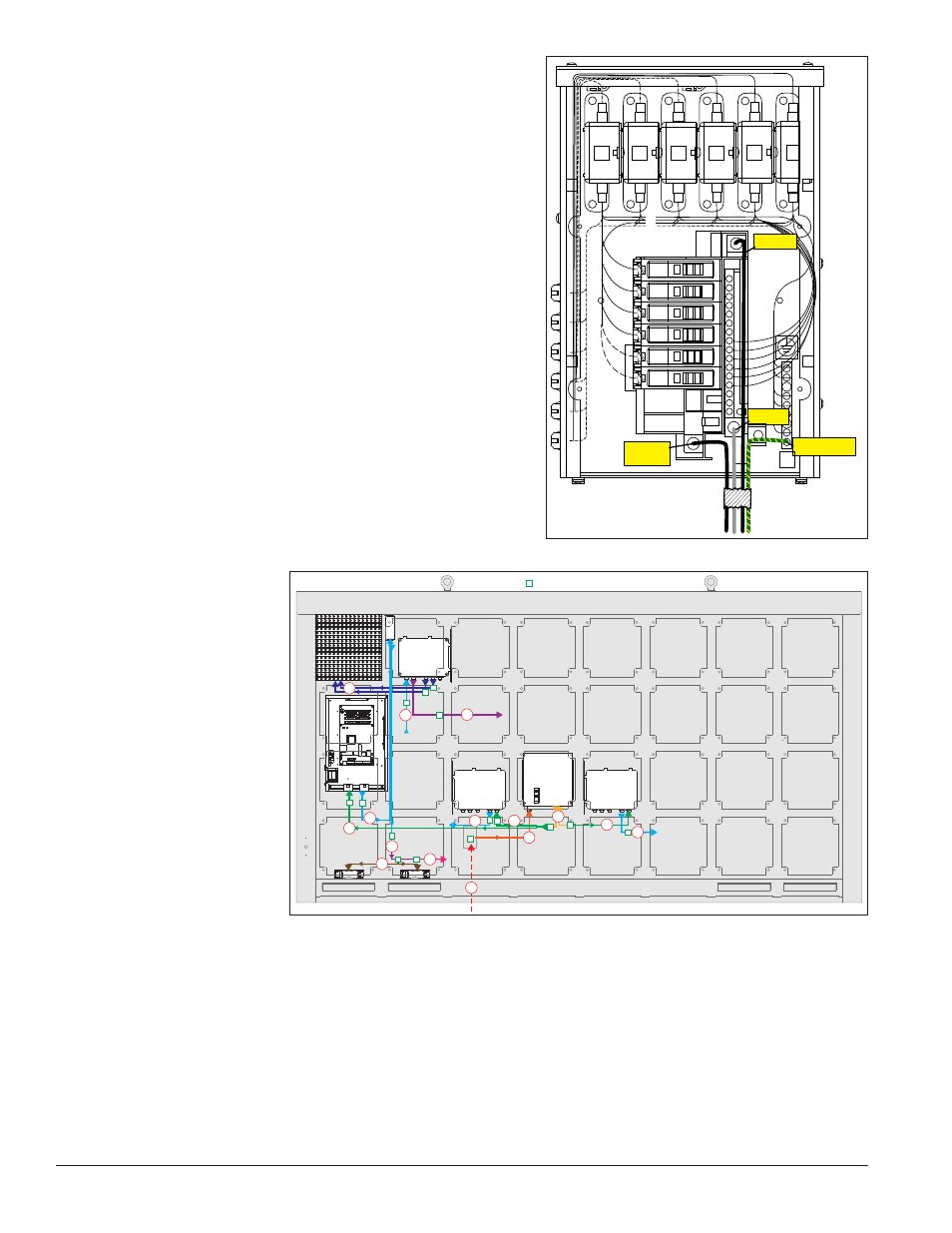
3.7 Power Routing in the Display
The following list corresponds to the numbers and letters in
1. Power enters the display from an external power
source, either through a rear-mounted J-box, or
directly through a cabinet knockout.
2. Power then
enters the
internal circuit
breaker box.
3. Power leaves
the circuit
breaker box
through wiring
harnesses
including a Y
harness that
sends power
to multiple
components.
4. a. Power travels
into the display
controller
enclosure.
b. Power travels
to power supplies.
5. a. Power leaves the display controller enclosure and travels to the thermostat.
b. Power leaves the power supply and travels to the following power supply.
c. Low voltage power leaves the power supply and travels to the display module.
One module per power supply connects to the voltage adjust cable.
15
15
15
15
15
15
GRN
WHT
BLK
GRN
Z1
Z2
Z3
Z4
Z5
Z6
LINE 1
NEUT.
E41
LINE 2
GROUND
Figure 7: Single-phase 6-breaker Domestic Panel
= Electrical Connector
1
2
3
4a
4b
5b
5a
5b
6a
6b
5c
4b
5b
7a
8a
Figure 8: Power Flow Summary