Section 1: introduction, 1 display details, Section 1 – Daktronics Galaxy AF-3220 User Manual
Page 5: Introduction, Display details
Introduction 1
Section 1: Introduction
This manual provides installation, maintenance and troubleshooting information to help ensure the optimal
performance of the Daktronics Galaxy
®
AF-3220 series display. Diagnostic and parts replacement information are also
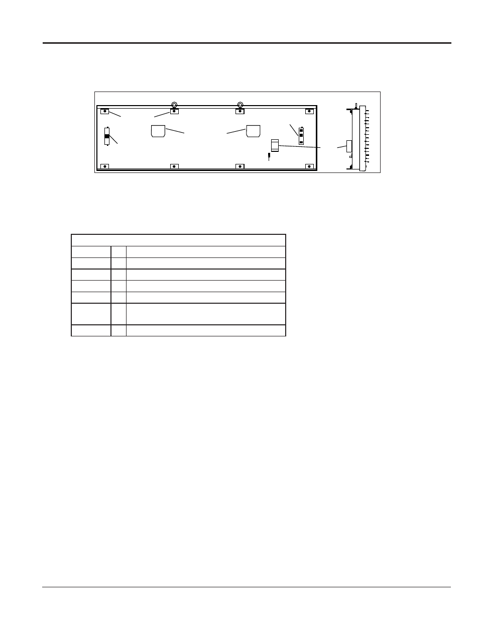
included. The back and side views of a typical display are shown in
1.1 Display Details
Galaxy
®
model numbers are described as follows:
The displays are offered as SF (single-face) or 2V (two-view) units. With a 2V (two-view) unit, the first display
is called the primary and the second display is referred to as the mirror. If the second display will be mounted
at a distance of more than 6 feet from the primary display, then two primary displays must be used.
A typical display system is controlled with a Windows
®
-based personal computer (PC) running Venus
®
1500
software.
Figure 1: Back and Side Views of a Typical Display
Back View
Clip Angles
Exhaust Vents
Signal Output
To Mirror Display,
If Present
Ground Lug
Quick-Connect
Signal Input Jacks
J Box
Side View
AF-3220-RRxCCC-34-R, A, RGB-XX
AF-3220
=
Outdoor Galaxy display
3220
=
Series Number of Display
RR
=
Number of pixel rows high (16 or 24)
CCC
=
Number of pixel columns long (up to 96 standard
34
=
Pixel pitch in millimeters
R, A, RGB =
LED Color: R (Red), A (Amber), RGB (Full Color
– Red, Green, Blue)
XX
=
SF (Primary) or 2V (Primary/Mirror)