Section 5: start-up procedure, 1 start-up checklist, 2 boot sequence – Daktronics Galaxy AF-3220 User Manual
Page 15: Section 5, Start-up procedure, Start-up checklist, Boot sequence
Start-Up Procedure
11
Section 5: Start-Up Procedure
Before starting the display, review the following checklist to ensure all parts are ready to operate correctly. Figure 1
shows the basic display components referred to in each step.
5.1 Start-up Checklist
• Confirm that power is correctly connected to the display
• Earth-ground electrode is installed with a resistance to ground of 10 ohms or less
• External communication equipment is properly installed
• Inspect signal connections at the control computer, display, and between display faces
• Confirm the control computer has Venus
®
1500 software installed and is correctly configured
• Inspect peripheral equipment (temperature sensor, etc.) for proper installation
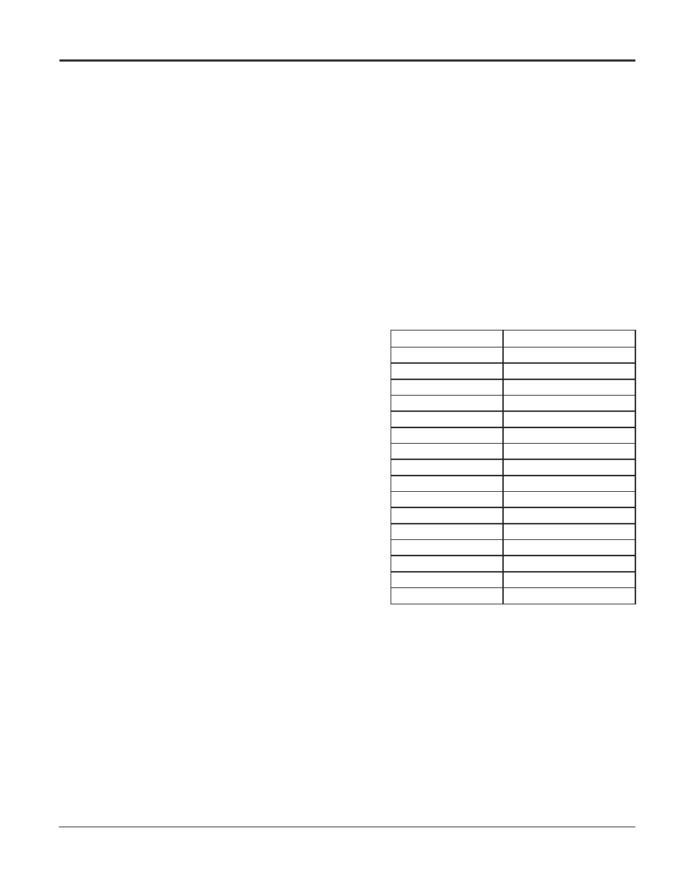
5.2 Boot Sequence
Each time the display is turned on, a boot sequence runs.
The information in the second column is shown on the
display.
Note: The Xs refer to numbers that may vary for each
display, such as the hardware address.
After this sequence is complete, a single pixel will flash
in the lower-right corner of the display to show that the
display has power and is ready for content.
Topic
Information Shown
Product Name
Galaxy®
Display Size
#Rows x #Columns
Shading
64 Mono or RGB 32k
Bootloader Version
OS XXX
Firmware Number
ED-13305
Firmware Revision
Rev X.XX
Hardware Address
HW:XX
Software Address
SW:XX
IP Address
(default: IP: 172.16.192.25
Subnet Msk
(default) MSK: 255.255.0.0
COM1 Configuration
C1:V15
COM 2 Configuration
C2: RTD
Socket 3001
IP 3001: V15
Socket 3002
IP 3002: RTD
Line Frequency
CLK: AUTO (60)
Display Description
Display 1