Controller replacement, Tools required, Figure 15: removing a module – Daktronics Galaxy AF-3220 User Manual
Page 24: Figure 16: typical controller
20
Replacement Parts
4. Unplug the power cable by squeezing the tabs on the sides of the plug head and pulling out.
5. Disconnect the two ribbon cables from the module by spreading the tabs on the sides and then lifting
the cable head from the jack.
6. Using a nut driver, remove the 10 nuts holding
the module to the panel. Refer to
7. To install a module, place it in position over the
bolts and use the nut driver to replace all nuts.
8. Reconnect the signal and power cables to the
module, making sure that the plugs make good
connections.
9. Carefully close the face panel. Latch the panel by
turning the fasteners a quarter turn clockwise.
*Be sure to fully close each individual latch to
ensure a water tight seal.
Controller Replacement
Tools required:
3
/
16
" nut driver
1. Turn off power to the display.
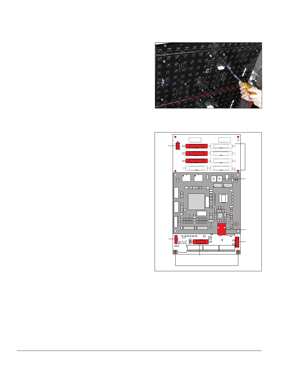
2. Open the face panel. The controller, shown in
Figure 16, is located in the lower-left corner of
the primary display.
3. Disconnect the power plug from power input
jack.
4. Remove all signal connections, carefully pulling
them from their jacks. Label the various cables
and wires as they are removed to insure their
proper replacement.
5. Remove the six screws holding the board in
place using the nut driver.
6. Take note of the address on the controller and set
the same address on the replacement controller.
7. Install the replacement controller using all six
screws removed, connect signal cables and
power connector
8. Turn on power to the display and observe the boot sequence. Once the sequence is complete, a single
pixel should flash in the lower-right corner of the display.
Figure 15: Removing a Module
UPPER LOWER
1 2
3
4
5
678
C
D
EF
9A
B
0
1 2
3
4
5
678
C
D
EF
9A
B
0
Power
Input
Module
Outputs
Address
Switches
Ethernet
Input
CAN
Input
Light
Sensor
Input
Quick-Connect Input
Mounting Nuts
Line 1
Line 2
Line 3
Figure 16: Typical Controller