Section 7: diagnostics and troubleshooting, 1 controller diagnostics, 2 troubleshooting display problems – Daktronics Galaxy AF-3220 User Manual
Page 19: Tools required for troubleshooting, Section 7, Diagnostics and troubleshooting, Controller diagnostics, Troubleshooting display problems, Diagnostics and troubleshooting 15, Figure/ label led # color operation run
Diagnostics and Troubleshooting
15
Section 7: Diagnostics and Troubleshooting
7.1 Controller Diagnostics
The controller is the “brains” of the display, receiving
communication from the computer and then sending the
appropriate information to the modules. LEDs on the
controller show whether the power and communication
signal are working correctly.
Since the controller is inside the display, open the face
panel to view the diagnostic LEDs, shown in
To access the interior of the display, refer to Section 6.1 for
instructions and illustration.
Remember to turn off power to the display before
accessing the interior.
However, once the door is open and the wires are found to
be safe, power can be turned back on to view the diagnostic
LEDs.
7.2 Troubleshooting Display Problems
This section contains some symptoms that may be encountered in the displays. This list does not include
every possible symptom or solution but does represent common situations and simple steps to resolve them.
The solutions are listed in priority order, so try the first solution first. If any of the steps referenced do not
solve the issue, contact Daktronics Customer Service.
Troubleshooting may require opening the display cabinet. Refer to Section 6.1 for instructions on this
procedure. Before closing the cabinet, make sure power and signal cables are reconnected correctly.
Tools Required for Troubleshooting:
•
5
/
32
" Hex wrench
•
Set of nut drivers
•
Flathead and Phillips screwdrivers
•
Service Laptop computer (recommended)
UPPER LOWER
1 2
3
4
5
678
C
D
EF
9A
B
0
1 2
3
4
5
678
C
D
EF
9A
B
0
DS4
Run
DS3
Transmit
DS2 Receive
Line 1
Line 2
Line 3
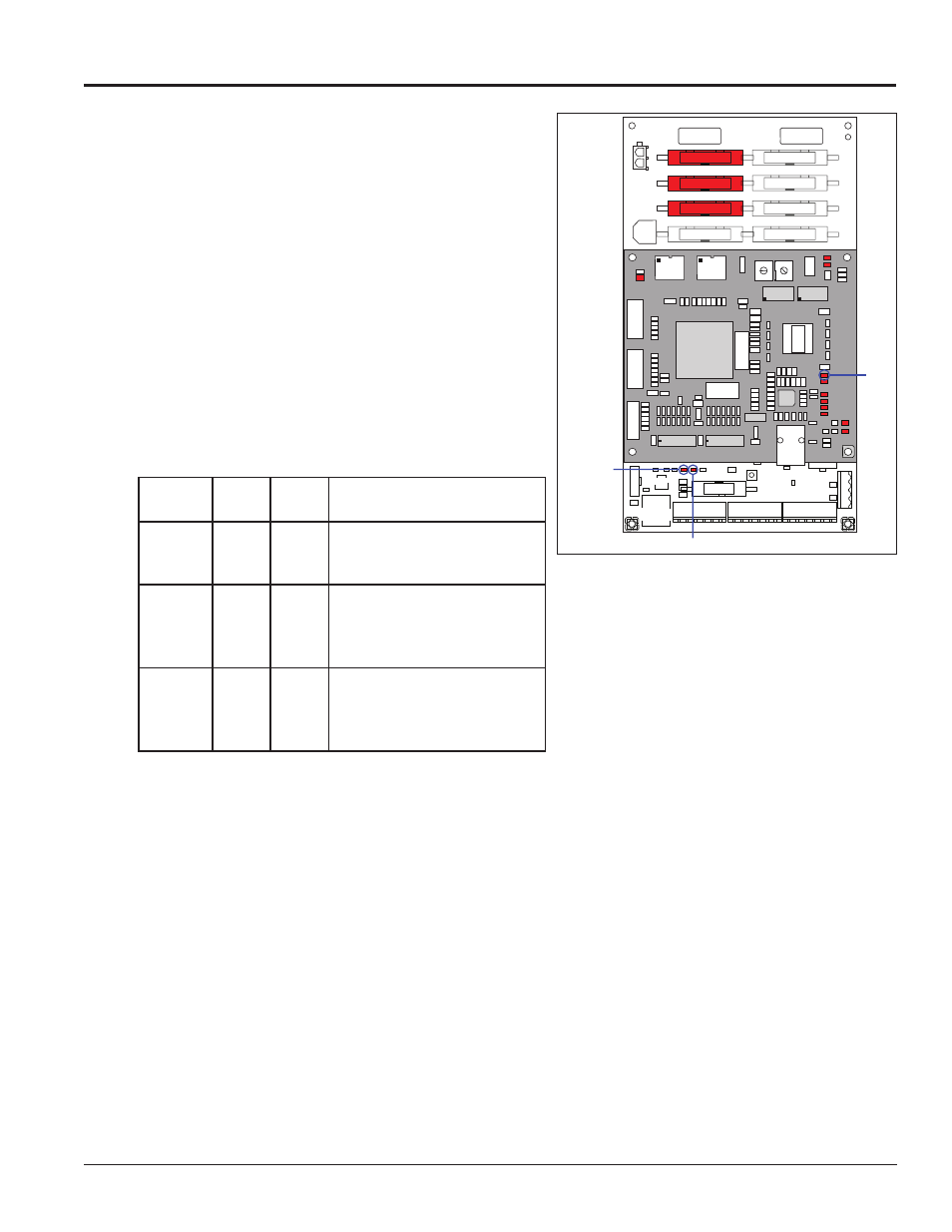
Figure 12: Controller Diagnostics
Figure/
Label
LED # Color Operation
Run
DS4
Red
Steady FLASH about once per
second indicates controller is
working properly.
Send
signal
TX
DS3
Yellow
OFF is the normal state.
FLASH when transmitting
serial communication from the
computer.
Receive
signal
RX1
DS4
Yellow
OFF is the normal state.
FLASH when receiving serial
communication from the
computer.