Controller address setting, Power supply replacement, Address upper lower – Daktronics Galaxy AF-3220 User Manual
Page 25
Replacement Parts
21
Controller Address Setting
The rotary switches set the hardware address of the controller. Each Primary
display in a network needs a unique address, as shown in
Figure 17. Each
controller in a network also needs a unique address.
Set the switches by rotating them counterclockwise until the arrow points to
the desired number. The display’s power must be turned off and then turned
back on to activate a change in the address.
Note: Setting both rotary switches to address 0 will activate a Test Mode.
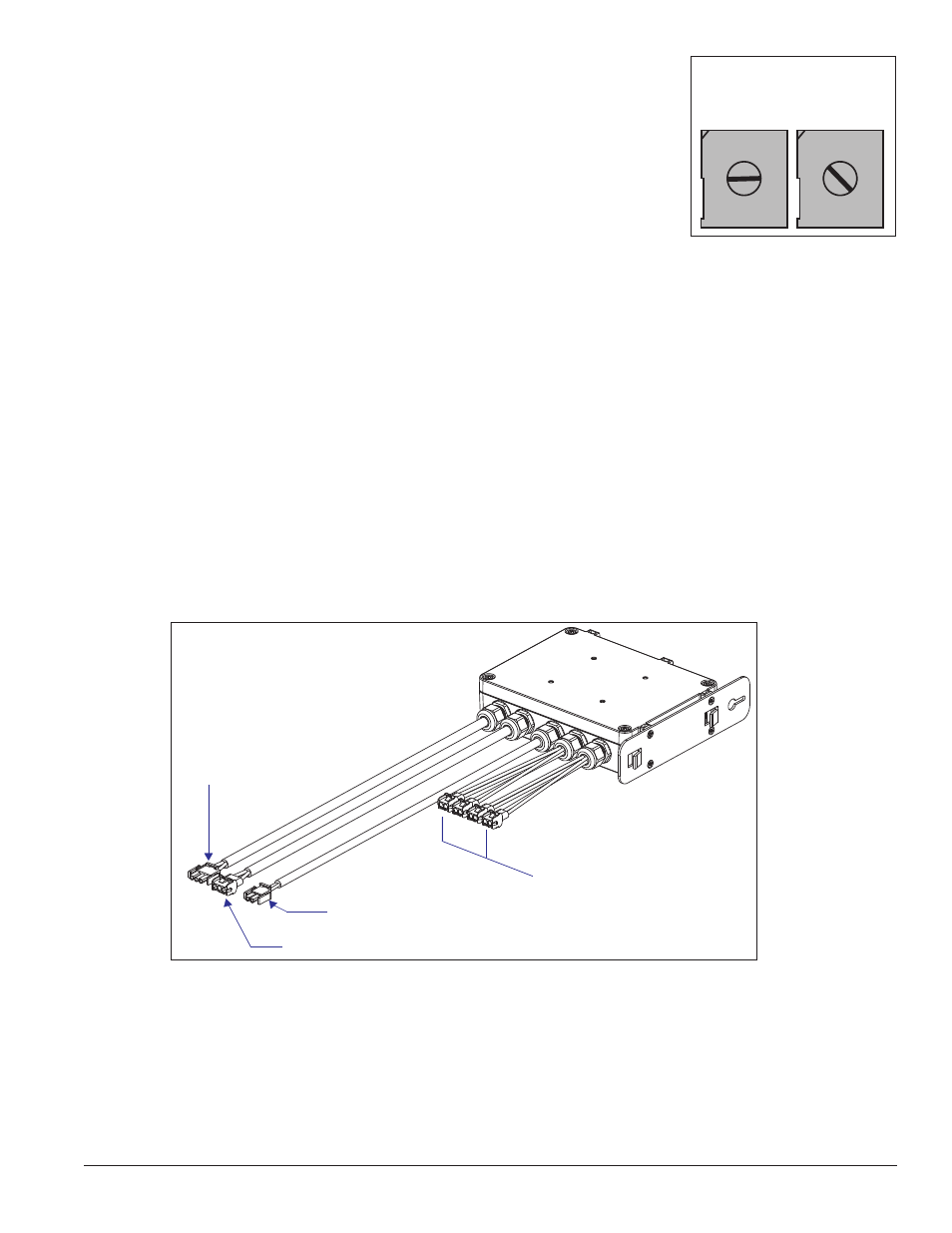
Power Supply Replacement
Tools required: Phillips screwdriver or nut-driver
Complete the following steps to replace a power supply:
1. Turn off power to the display.
2. Access the interior of the display by opening the face panel.
3. Disconnect the Mate-n-Lok
®
connectors from the power source as well as those going to the modules.
Be sure to label each connector so that it can be properly reconnected.
4. Loosen, but don’t remove, the screw holding the power supply bracket to the cabinet upright and lift
off the hooks.
5. Move the new power supply into place and tighten the screw on the support bracket.
6. Reconnect all the Mate-n-Lok
®
plugs.
1 2
3
4
5
678
C
D
EF
9A
B
0
1 2
3
4
5
678
C
D
EF
9A
B
0
ADDRESS
UPPER LOWER
Figure 17: Rotary Switches
DC Outputs (To Modules)
AC Input
(From Power
Source)
AC Output (To Next Power Supply)
V Adjust (To Initial Module)
Figure 18: Power Supply