2 program selection, Program selection – Daktronics PC-2001 Pace Clock System User Manual
Page 16
10
Controls & Timing Functions
4.2 Program Selection
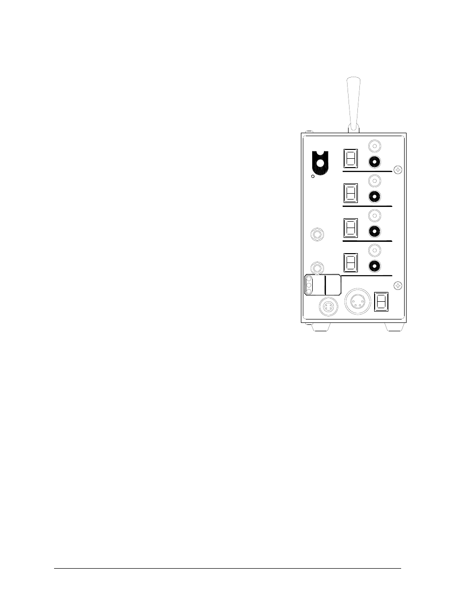
The Model PC-2001 display is programmable for 11 different
timing programs. The operator selects each program and
makes settings for the functions using the switches on the
right side of the display. Figure 8 shows the PC-2001 control
panel and programming connections.
To select a program:
1. Press and hold <RESET> for 2 seconds.
The display will show PR## (program number) and
then the preset time.
2. While holding <RESET>, press and release
<HORN> to increment the program number by one.
Program numbers are as follows:
1) Breakout Timer
2) Start Reaction Timer w/ Omega Relay Take-Off
Platform
3) Backstroke Start Reaction Timer
4) Relay Exchange Timer w/ Omega Relay Take-
Off Platform
5) Pace Clock
6) Game Clock
7) Shot Clock
8) 12-hour Time of Day
9) 24-hour Time of Day
10) Start Reaction Timer w/ Daktronics Relay Take-
Off Platform
11) Relay Exchange Timer w/ Daktronics Relay
Take-Off Platform
Note: Refer to Section 4.3 for more information about each program.
To modify the preset time for programs 1, 5, 6, and 7:
1. Press and hold <RESET> for 2 seconds. The display will show PR## (program
number) and then the preset time.
2. While holding <RESET>, press <START> to increment minutes and press <STOP>
to increment seconds.
3. Release <RESET> to save the time. The display will count up to or down from that
time, depending on the selected program.
To set the time of day for programs 8 and 9:
1. Press and hold <RESET> for 2 seconds. The display will show PR## (program
number) and then the preset time.
2. While holding <RESET>, press <START> to increment hours and press <STOP> to
increment minutes.
3. Release <RESET> to save the Time of Day.
P
C-20
01
AUX.
RES
ET
BU
TTO
N
PL
ATFO
RM
H
ORN
S
TART
POWER
TO
UC
HP
AD
RESET
(SHIFT)
HORN
(INCREMENT PROG. #)
STOP
(INCREMENT MINUTES)
(INCREMENT HOURS)
START
OFF
ON
12V IN
SIGNAL OUT
SIGNAL IN
STATUS
BATTERY
CHARGE
LOW
FULL
PORT
D
AK
TR
ON
IC
S
R
Figure 8: Control Panel