3 replacing digits, Segmentation & digit designation, Replacing digits – Daktronics MS-2013 Portable LED Scoreboard User Manual
Page 26: N 6.3 )
20
Scoreboard Troubleshooting
6.3 Replacing Digits
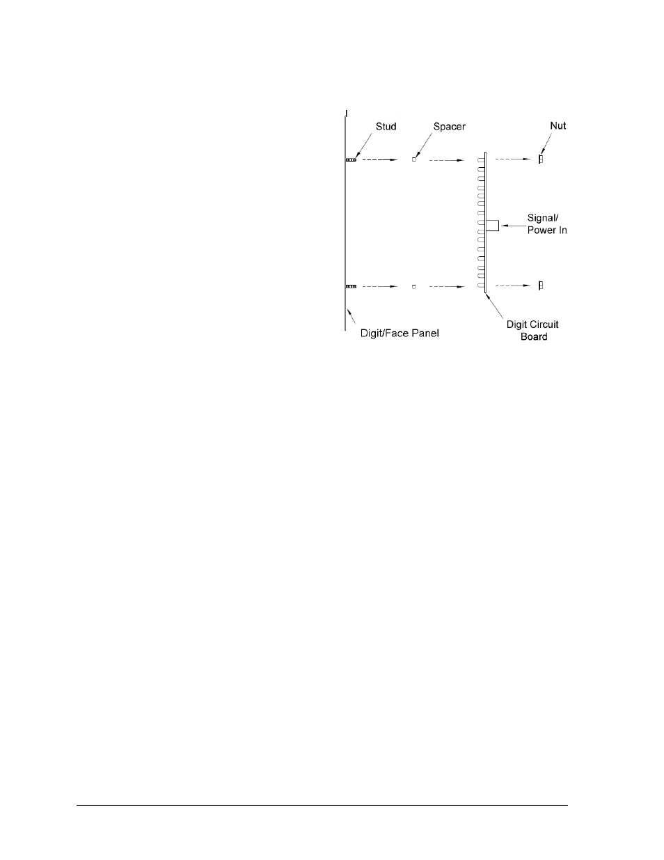
LEDs are embedded in a circuit board that is
mounted to the back of a single face panel,
as shown in Figure 9. Do not attempt to
remove individual LEDs. In the case of a
malfunctioning LED or digit segment,
replace the entire digit circuit board.
To replace a digit circuit board:
1. Open the back panel as described in
Section 6.2.
2. Disconnect the power/signal plug
from the back of the digit by
squeezing together the locking tabs
and pulling the connector free.
3. Use a
9
/
32
" nut driver to remove the
nuts securing the digits to the inside
of the panel, and then lift the digit
off the standoff studs.
4. Position a new digit over the studs, making sure the rubber side of the rubber-backed
spacer is facing the digit circuit board.
5. Tighten the nuts.
6. Reconnect the power/signal connector.
Note: This is a keyed connector and it will attach in one way only. Do not attempt to
force the connection.
7. Close and secure the back panel, then power up and test the scoreboard to see if
changing the digit has resolved the problem.
Segmentation & Digit Designation
Reference Drawings:
Segmentation, 7 Segment Bar Digit ........................................................................ A-38532
Electrical Specifications, MS-2013 ........................................................................ A-159887
In each digit, certain LEDs always go on and off together. These groups of LEDs are called
segments. Drawing A-38532 in Appendix A details which connector pin is wired to each
digit segment and the wiring color code used throughout the scoreboard.
Drawing A-159887 in Appendix A indicates the driver connectors controlling the digits.
The numbers shown in the upper half of a digit indicate which driver connector is wired to it.
Figure 9: Digit Assembly