Auxiliary 1 connector and pinouts (j9) – Comtech EF Data SDM-300L User Manual
Page 38
SDM-300L Satellite Modem
Installation
Rev. 2
2–17
Auxiliary 1 Connector and Pinouts (J9)
The auxiliary 1 (AUX 1) connector provides:
•
MOD and DEMOD (TTL) faults
•
Satellite
clock
•
Satellite
I&Q
•
Automatic Gain Control (AGC) output voltage
The faults are open collector levels that indicate a modulator or demodulator failure. A
logic “1” indicates the faulted condition.
AGC_OUT is a programmable voltage, 0 to 10V, for a receive signal level between
-25 and -60 dBm.
AUX 1 connection is a 9-pin female D connector (J9) located on the rear panel of the
modem. Screw locks are provided for mechanical security on the mating connector. Refer
to Table 2-9 for pinout information.
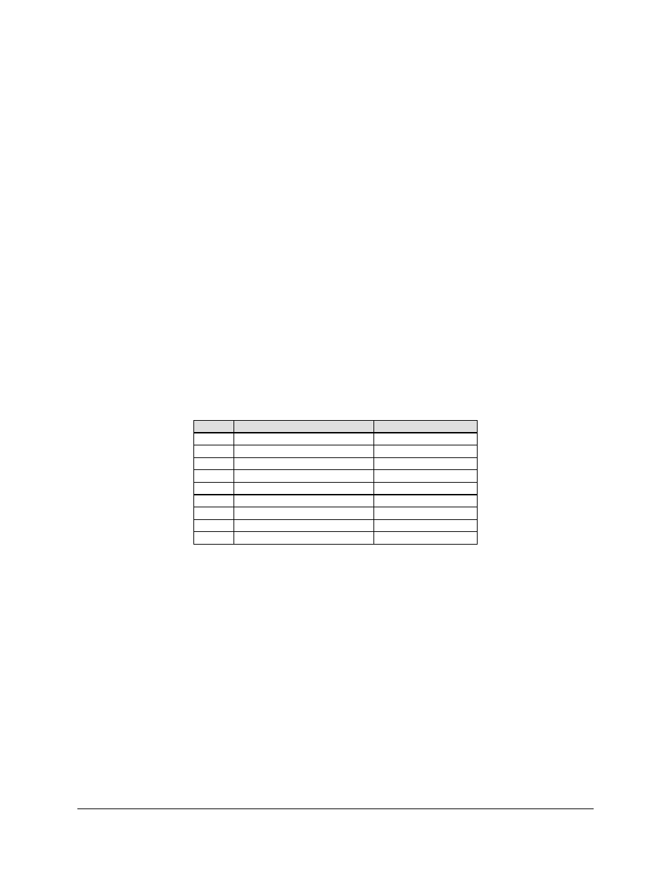
Table 2-9. AUX 1 Connector and Pinouts (J9)
Pin #
Signal Function
Name
1
Satellite Clock -
SAT_CLK-
2 No
Connection
NC
3
Satellite Clock +
SAT_CLK+
4
MODULATOR TTL Fault
MDFLTTTL
5 Ground
GRN
6
RX_Q
RX Q Channel Eye
7
DEMODULATOR TTL Fault
8
RX 1 Channel Eye
RX_1
9
AGC Output
AGC
- CDD-880 (124 pages)
- CDM-800 (130 pages)
- ODMR-840 (184 pages)
- CDM-750 (302 pages)
- CDM-840 (244 pages)
- SLM-5650A (420 pages)
- CTOG-250 (236 pages)
- CDM-700 (256 pages)
- CDM-760 (416 pages)
- CDM-710G (246 pages)
- CDM-600/600L (278 pages)
- CDMR-570L (512 pages)
- CDM-625 (684 pages)
- CDM-625A (756 pages)
- CDD-564A (240 pages)
- CDD-564L (254 pages)
- CLO-10 (134 pages)
- MCED-100 (96 pages)
- CDMR-570AL (618 pages)
- CDM-600 LDPC (2 pages)
- BUC Power Supply Ground Cable (2 pages)
- MPP70 Hardware Kit for CDM-570L (4 pages)
- MPP50 Hardware Kit for CDM-570L (4 pages)
- CDM-625 DC-AC Conversion (4 pages)
- CDM-625 DC-AC Conversion with IP Packet Processor (4 pages)
- DMDVR20 LBST Rev 1.1 (117 pages)
- DMD2050E (212 pages)
- DMD-2050 (342 pages)
- DMD1050 (188 pages)
- OM20 (220 pages)
- QAM256 (87 pages)
- DD240XR Rev Е (121 pages)
- MM200 ASI Field (5 pages)
- DM240-DVB (196 pages)
- MM200 (192 pages)
- CRS-150 (78 pages)
- CRS-280L (64 pages)
- CRS-170A (172 pages)
- CRS-180 (136 pages)
- SMS-301 (124 pages)
- CiM-25/8000 (186 pages)
- CiM-25 (26 pages)
- CRS-500 (218 pages)
- CRS-311 (196 pages)
- CIC-20 LVDS to HSSI (26 pages)