External modem connections, 3 external modem connections – Comtech EF Data SDM-300L User Manual
Page 25
Installation
SDM-300L Satellite Modem
2–4
Rev.
2
2.3
External Modem Connections
When a breakout panel, such as the UB-530, is not required, the rear panel connectors
provide all necessary external connections between the modem and other equipment.
Table 2-1 lists these connectors, and Figure 2-2 through Figure 2-5 show their locations.
Notes:
1. Refer to the Comtech EFData UB-530 Universal Breakout Panel Installation
and Operation Manual for connecting the UB-300 breakout panel.
2. Refer to the Comtech EFData UB-54 Breakout Panel Installation and Operation
Manual for connecting the UB-54 breakout panel in a MUX option
configuration.
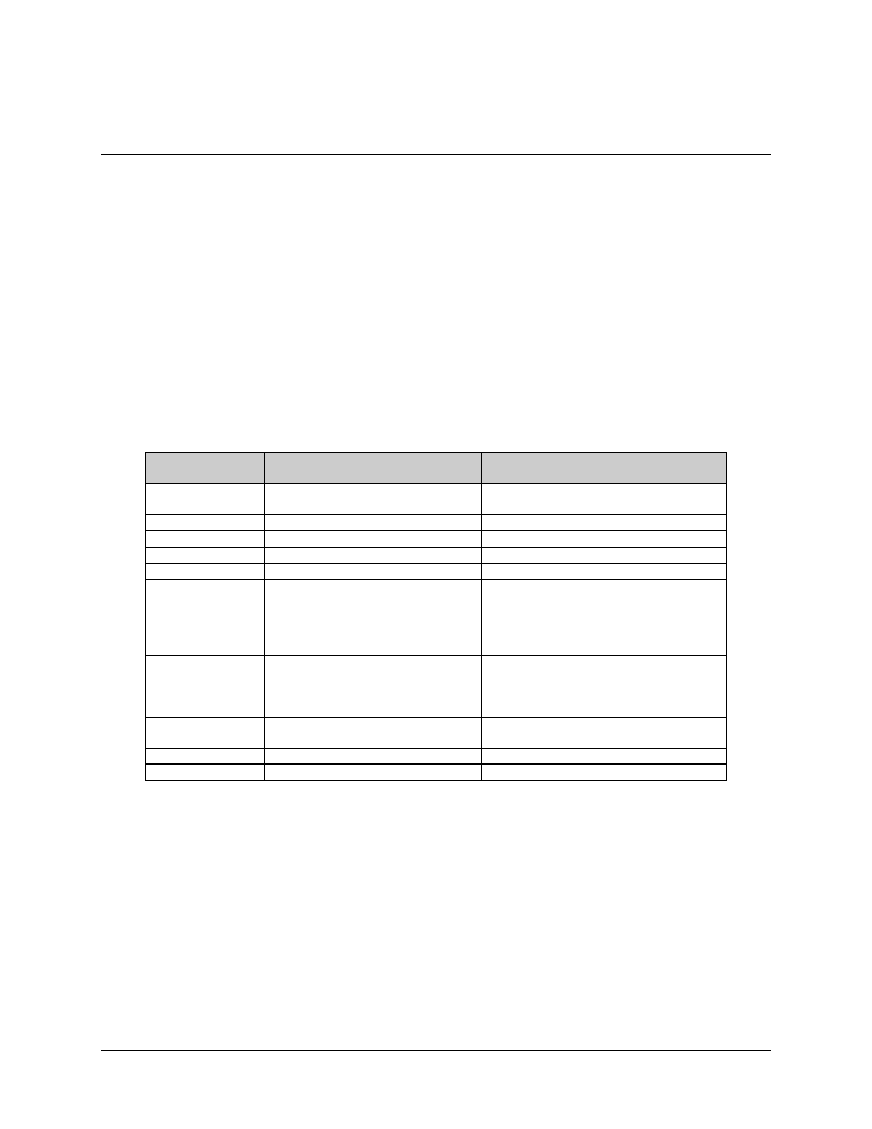
Table 2-1. Modem Rear Panel Connectors
Name
Ref.
Desig.
Connector Type
Function
TX/IF OUTPUT
CP1
BNC (70/140 MHz)
Type N (L-Band)
RF Output
EXT REF
CP2
BNC
EXT REF IN
RF IF INPUT
CP3
Type N 75
Ω
RF Input
REMOTE
J6
9-pin D
Remote Interface
FAULT
J7
9-pin D
FORM C Fault Relay Contacts
DATA I/O
J8
25-pin D
34-pin
37-pin D
50-pin D
Data Input/Output (standard modem)
V.35
EIA-449
Data Input/Output (modem with
ASYNC/AUPC/IDR/IBS option)
AUX 1
J9
9-pin D
(TTL) Faults
Satellite Clock
Demod I/Q
Automatic Gain Control (AGC) Out
ALARMS
J10
9-pin D
FORM C Alarm
Relay Contacts
AC INPUT
NONE
IEC
GROUND NONE
10-32
Stud
Note: The European EMC Directive (EN55022, EN50082-1) requires using properly shielded
cables for DATA I/O. These cables must be double-shielded from end-to-end, ensuring a
continuous ground shield.