Figure 1-2. block diagram – Comtech EF Data SDM-300L User Manual
Page 13
Introduction
SDM-300L Satellite Modem
1–2
Rev.
2
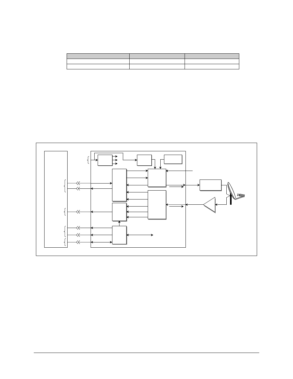
Table 1-1. SDM-300L Versions
Type
Transmit (TX)
Receive (RX)
SDM-300L-1 70/140
MHz
L-Band
SDM-300L-2 L-Band L-Band
Refer to Figure 1-2 for a system block diagram.
Notes:
1. The UB-530 universal breakout panel (BOP) is an option for V.35, G703,
EIA-232, and EIA-422.
2. When the modem is equipped with a 50-pin data I/O connector, the use of the
BOP is required to interface the customer data connector to the modem.
3. Contact Comtech EFData for information concerning universal breakout panels.
M&C
M&C
Remote Port
Alarm Relays
Fault Relays
J7
J10
J6
J9
Data
Interface
Data
Interface
Tx Data
Tx Clock
ST Clock
Rx Data
Rx Clock
Demodulator
/ Decoder
Demodulator
/ Decoder
Encoder /
Modulator
Encoder /
Modulator
I/Q
Sat Clock
AGC
AUX 1
AUX 1
AUX 1
Control / Status
Tx IF
Ext Ref
Rx IF
CP1
CP2
CP3
Ref Osc
Ref Osc
Power
Supply
Power
Supply
Transmit
RF Equipment
Transmit
RF Equipment
LNB
LNB
SDM-300L Satellite Modem
(Optional)
Breakout Panel
UB-530
J8
User
Data
AUX 1
OC-TTL
Faults
Form C
Contacts
Remote
Port
AC Or
Optional
DC
Prime
Power
Note 1
Notes:
1) Tx IF (L-Band only) Outputs a 10 MHz
Reference and Optional ODU Voltage.
2) Rx IF Outputs LNB Voltage and 10 MHz
Reference.
Note 2
Opt ODU
Supply
Opt ODU
Supply
AC Only
Figure 1-2. Block Diagram