Comtech EF Data CME-5000 Manual User Manual
Page 33
Digicast Micro Encapsulator (MENCAP)
Revision A
Installation & Initial Configuration MN/MENCAPEDC.IOM
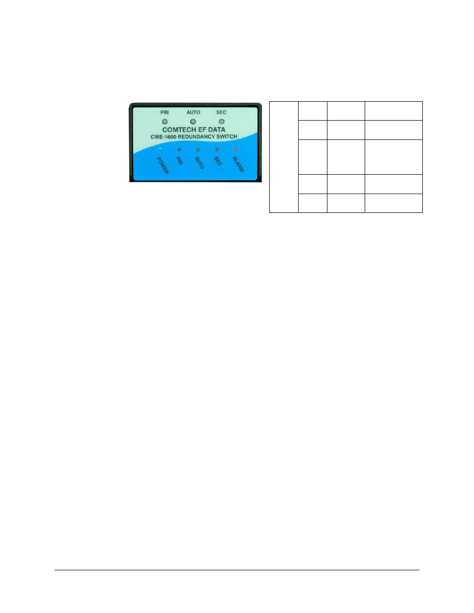
Figure 2-2 shows the LED status displayed on the CME-1600 Redundancy Switch once
the unit has been configured for basic operation.
Figure 2-2. LED Status of CME-1600 Redundancy Switch (after configuration)
At this point, the unit has been configured for basic operation and the terminal cable may
be removed. The ASI cable may now be safely attached to one of the two (mirrored)
output ports. For continued operation the unit may be managed via the Terminal
Interface; however, it is recommended to use the Web Interface for ease of management.
Blue POWER
Power
normally on
Green PRI
Primary unit
normally on
Green AUTO
Auto
Redundancy
mode
normally on
Green SEC
Secondary unit
normally off
LEDs
Red ALARM
Alarm
normally off
2-7