Mph/kph, Gear shift indicator inputs, The park, reverse, ntrl, ovrdrv, drive, 2 – Dakota Digital SERIES II STR3D User Manual
Page 10: And 1
10
MPH/KPH
The MPH/KPH terminal is activated by a 12 volt signal from a push button or toggle
switch(not supplied). When the display system is in English mode (MPH &
°
F) by placing DIP
programming switch #7 off, applying 12 volts to this terminal will convert the speed reading from
MPH to KPH. The odometer will continue to accumulate miles correctly, but will display dashes.
The bar speed display, if present, will not be affected.
When the display system is in Metric mode (KPH &
°
C) by placing DIP programming
switch #7 on, applying 12 volts to this terminal will convert the speed reading from KPH to MPH.
The odometer will continue to accumulate kilometers correctly, but will display dashes. The bar
speed display, if present, will not be affected.
This input is provided to allow a convenient method of switching from MPH to KPH or
from KPH to MPH while crossing borders or driving in areas with different speed markings.
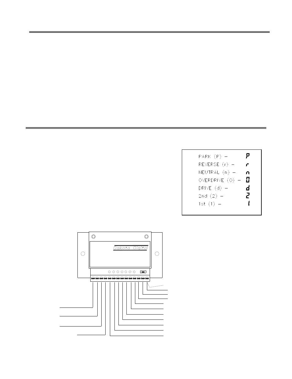
GEAR SHIFT INDICATOR INPUTS
The PARK, REVERSE, NTRL, OVRDRV, DRIVE, 2
nd
,and 1
st
terminals are used for the
gear shift indicator. The inputs are activated be a 12 volt signal from a gear shift sending unit.
The indicator is built into every system but it will not light up
unless a Dakota Digital GSS-1000 or compatible gear shift
sending unit is connected to tell it what gear the
transmission is in. The gear shift sending unit is not
included with the system and must be purchased separately.
When the gear shift sending unit is connected, a letter
will light up to the right of the odometer to indicate what gear
the transmission is in. Below is a chart showing the display
indicators for each of the gears and a wiring diagram using
Dakota Digital’s GSS-1000 adjustable gear shift sending
unit. If you have a different gear shift sending unit, consult
the wiring instructions supplied by the manufacturer.
S
a
fe
ty
D
ri
v
e
GSS-1000
DECODER
P
a
rk
B
a
c
k
u
p
P
o
w
e
r
D
im
R
e
v
e
rs
e
N
e
u
tr
a
l
O
v
e
rd
rv
S
ig
n
a
l
H
I
S
e
c
o
n
d
F
ir
s
t
G
ro
u
n
d
do not connect
(optional)
+12V
(optional)
to control box SECOND terminal
to control box OVERDRIVE terminal
to control box DRIVE terminal
to control box NEUTRAL terminal
to control box REVERSE terminal
to control box PARK terminal
to Chassis Ground
to sensor BLACK wire
to sensor GREEN wire
to sensor RED wire
to control box FIRST terminal