Caple CM400FA User Manual
Page 13
43
UK
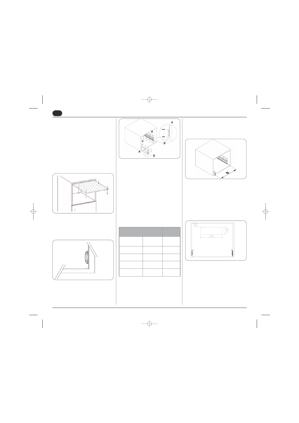
• The machine is supplied with 6 metal plates
(thickness 1 mm) that are to be placed
between the guide and the sides of the unit.
This is to fill any excess space in the event
that the unit is more than 562 mm wide.
5.4
NUMBER OF SPACER
PLATES
• If necessary, insert the plates as described
above.
• Make sure that there is a distance (distance
B) of 558 mm between the corner pieces.
• Fix the guides to the coffee machine hous-
ing, tightening all of the screws.
• Make sure that the power cord comes out
from the rear of the housing.
• To prevent the machine from overheating,
make an opening in the back of the unit of at
least 300 mm x 100 mm, to allow air to cir-
culate.
• Insert the coffee machine into the unit, fitting
the guides on the machine level into the
guides previously fixed on the unit.
The guides should slide telescopically when
a light pressure is exerted on the front of the
coffee machine; if this is not the case, it is
necessary to check the distance between
BUILT-IN HOUSING
N°
PLATES
Width
(mm/inc)
Thick.
(mm/inc)
562 / 22,13
19 / 0,748
0
564 / 22,2
18 / 0,708
1+1
566 / 22,28
17 / 0,669
2+2
568 / 22,36
16 / 0,629
3+3
• Remove the coffee machine from its pack-
aging and make sure that it is not damaged
in any way. Should the machine show any
signs of damage, do not proceed with instal-
lation and contact the retailer.
5.3
BUILT-IN
INSTALLATION
• Place the metal plate in position in the top
part of the coffee machine housing so that it
meets with the back section of the unit.
• Tighten the four screws.
• Place the two corner pieces with guides on
the flat surface in the unit, fixing them into
place exactly 90 mm from the unit’s front
edge.
• Insert the screws into the holes of the corner
pieces, but do not tighten them..
SCM5
SCM5_UK_Rev_2.qxp 23/01/2008 15.58 Pagina 43