BUG-O Systems BGW-5000 User Manual
Page 32
32
V. WELDING PROCEDURE GUIDELINES
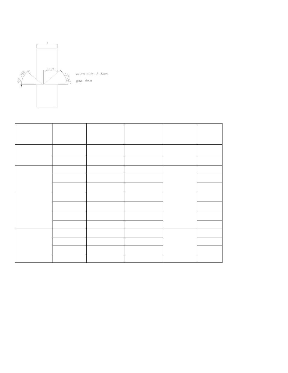
5.1 Joint Design
5.2 Typical Welding Parameters (for 3.2mm wire)
Wall
Thickness
(mm)
Voltage (V)
Amp (A)
Travel Speed
in/min
(mm/min)
Torch Angle
Shell
Course
10-14
26-27
320-350
15-17 (380-420)
15°-20°
1st
27-29
450-480
19-20 (480-520)
2nd
16-18
26-27
380-420
15-18 (380-450)
15°-20°
1st
27-29
450-480
19-20 (480-520)
2nd
28-31
450-520
20-26 (500-650)
3rd
20-22
26-27
380-420
15-18 (380-450)
15°-20°
1st
27-29
450-480
19-20.5 (480-520)
2nd
28-31
450-520
20-26 (500-650)
3rd
28-31
470-520
22-26 (550-650)
4th
24-32
26-27
380-420
15-18 (380-450)
15°-20°
1st
27-29
450-480
19-20 (480-520)
2nd
28-31
450-520
20-26 (500-650)
3rd
28-31
480-520
22-26 (550-650)
4th & up
Note: The serviceability of a product or structure utilizing the information in these guidelines must be the
sole responsibly of the builder. Many variables in design, fabrication and service conditions affect the results
obtained in applying this type of information. BUG-O systems is not responsible for any welding parameters
or guidelines for the BGW machines and or the SAW process.
Please have all parameters for SAW provided prior to the beginning of setup of machines.
We do offer a starting guide for parameters in our instruction manual, this is just a guide and not an exact set
of parameters to be followed.