7..... setup and operation, Setup and operation – BUG-O Systems CB-1P User Manual
Page 6
6
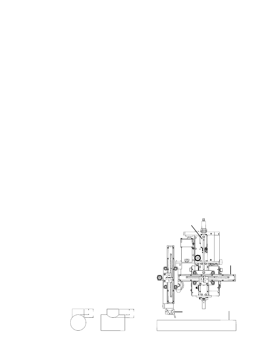
CAM
TORCH
HOLDER
PIPE
B A
B A
SETUP AND OPERATION:
**All page numbers referred to in this section are from this manual unless otherwise specified.**
POWER SUPPLY:
The CB-1P Plasma Circle Burner is supplied with a modified Thermal Dynamics CutMaster
®
82 Plus
Plasma Cutting Power Supply. The power supply provides auxiliary power to the CB-1P Plasma Circle
Burner for the operation of switches, speed control, and the rotational drive. Refer to the Thermal
Dynamics CutMaster
®
82 Plus Plasma Cutting Power Supply operating manual #0-4979 supplied with
this machine for general operation and set-up information.
PLASMA CUTTING TORCH:
The CB-1P Plasma Circle Burner is equipped with a Thermal Dynamics Plasma Cutting Torch model
PCM-120 machine torch. Refer to the Thermal Dynamics Plasma Cutting Torch instruction manual #0-
2818 supplied with this machine for general operation and set-up information.
FIXTURING:
All circle burners have to be fixtured in some manner from the top of the shaft. This may be achieved in
one of the following: column & boom, manipulator, or carriage & monorail.
CABLE CONNECTIONS:
The CB-1P Plasma Circle Burner is equipped with a Junction Box Assembly (CWO-3035), shown on
page 17. The Junction Box Assembly is supplied with five leads that need to be connected as described
below.
Connect:
• Plasma Box Cable Assembly to the terminal connector in the main gear at the top of the machine.
• Air Hose Assembly to the hose fitting in the top of the CB-1P Shaft Assembly item (11) on page 13.
• Low Frequency Power Cable to the Low Frequency Power Cable.
• High Frequency Power cable to the High Frequency Power Cable.
• The Power Supply Torch Lead (air, control cable, high frequency)to the power supply.
• It is helpful to mount the Junction Box assembly to the top of the carriage or to the manipulator.
EXAMPLE:
Let A=3 and B=2
3-2=1
The cam setting is 1.
RISE AND FALL OF THE CAM:
All circle burners are equipped with a rise and fall cam assembly.
The cam assembly must be aligned before any other settings can
be made. To align the cam on the machine, align the horizontal rack
parallel to the pipe, then adjust the gun holder so it is perpendicular
to the horizontal rack. Loosen the set screws in the brass block
on the cam, and rotate the cam to the vertical position as shown.
SETTING THE CAM:
The cam setting is equal to the distance “B” subtracted from the
distance “A”.
HORIZONT
AL
RACK