Beisler 739-23-1 Program User Manual
Page 34
4-34
2.6
Dacs739 tutorial
This practical tutorial allows you to familiarize yourself with the
Dacs739 software within a very short time. It covers all the basic steps
that must be carried out for the creation and archiving of your own
individual contours.
The tutorial includes additional information on any given topic and
indicates, where the respective chapter can be found in the online help
facility of Dacs739.
Dacs739 support multi-tasking so that several documents can be
processed simultaneously.
2.6.1
Creation of a seam contour
–
Start the Dacs739 software
(see chapter 2.4).
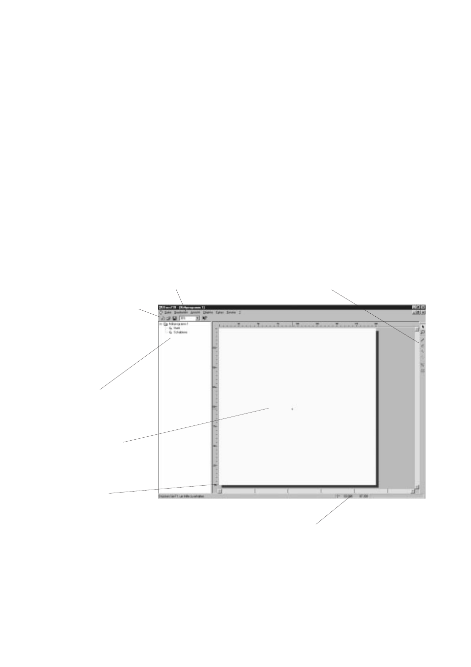
The programme window is opened.
–
Select “File > New”.
The document window is divided into two parts.
To the left, a tree diagram is displayed, showing the sections of the
seam contour. To the right, a CAD design window for the seam contour
to be drawn is displayed.
Below the menu bar, the “standard” toolbar is displayed, while the
“drawing” toolbar is located to the right. At the bottom of the screen,
the “status bar” is displayed.
Menu bar
“Drawing” toolbar
“Standard" toolbar
Tree diagram
Entry field for the
seam contour
Zero point P0
Origin of the
system of coordinates
Status bar
The zero point P0 is the origin of the coordinates system. It is always
located in the bottom left corner of the CAD window. The coordinates
run from this point, increasing upwards and to the right.