Maintenance – Beisler 1282-4 User Manual
Page 55
Closing Seam Machine 1282-4 Working Instructions
- 26 -
Beisler Automated Sewing Equipment
C.5
Maintenance
C.5.5 Settings
Installation stepper motor:
The PCB for controlling the stepper motor is installed in
the control box.
NOTE - Machine cycle!
To prevent moving machine parts from colliding with each
other or with other components when the machine is swit-
ched on again, move the machine manually into its start
position before the PCB is replaced.
1. Depressurize the compressed air system of the ma-
chine. Disconnect the compressed air hose of the ma-
chine from the on-site compressed air supply system.
2. Slide main clamp into start position.
CAUTION - Damage to electrical components!
The PCB switches must not be tampered with while
voltage is applied to the machine.
Otherwise, related electrical components may be
damaged or become unusable!
Disconnect machine from power supply system and
protect it against accidental reconnection.
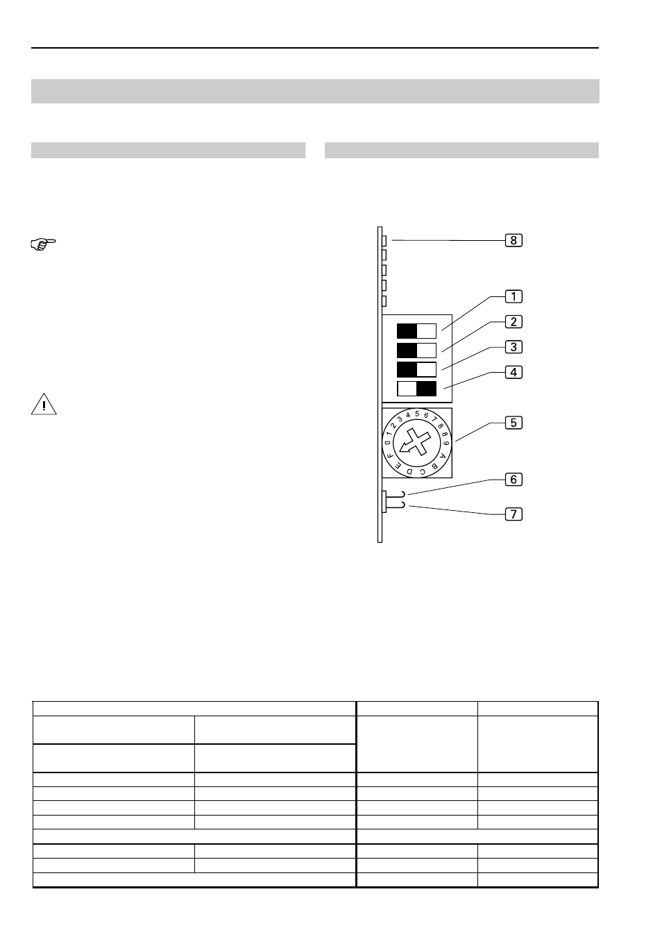
Adjusting switches on the PCB:
1. Set step width:
• using DIP switches
1
and
2
,
• micro step at hook switches
6
and
7
.
2. Set current lowering using DIP switch
3
.
3. DIP-switch
4
to ON.
4. Set motor phase current, rotate switch
5
to F.
5. Switch on supply voltage. When the PCB is adjusted
correctly, the LED
8
(stand-by) is illuminated, the
stand-by relay is energized.
Fig. 1
Fig. 1
DIP switch 1
DIP switch 2
200
2000
ON
OFF
400
4000
ON
ON
500
5000
OFF
ON
1000
100000
OFF
OFF
Rotary switch position
Phase current
DIP switch 3
Current lowering
F
5,50 A
OFF
ON
ON
OFF
Micro step
Signal 0 = deenergized, Signal 1 = energized
Hook switch
open
Signal = 0
Hook switch
closed
Signal = 1
Hook switch
closed
Signal = 0
Hook switch 6 open
Signal = 1