4 appendix, 1 mapping in the bus coupler – BECKHOFF KL1501 User Manual
Page 17
Appendix
KL1501
15
4 Appendix
As already described in the chapter terminal configuration, each bus
terminal is mapped in the bus coupler. In the standard case, this mapping
is done with the default setting in the bus coupler / bus terminal. This
default setting can be modified with the KS2000 configuration software or
using master configuration software (e.g. ComProfibus or TwinCAT System
Manager). The following tables provide information on how the KL1501
maps itself in the bus coupler depending on the set parameters.
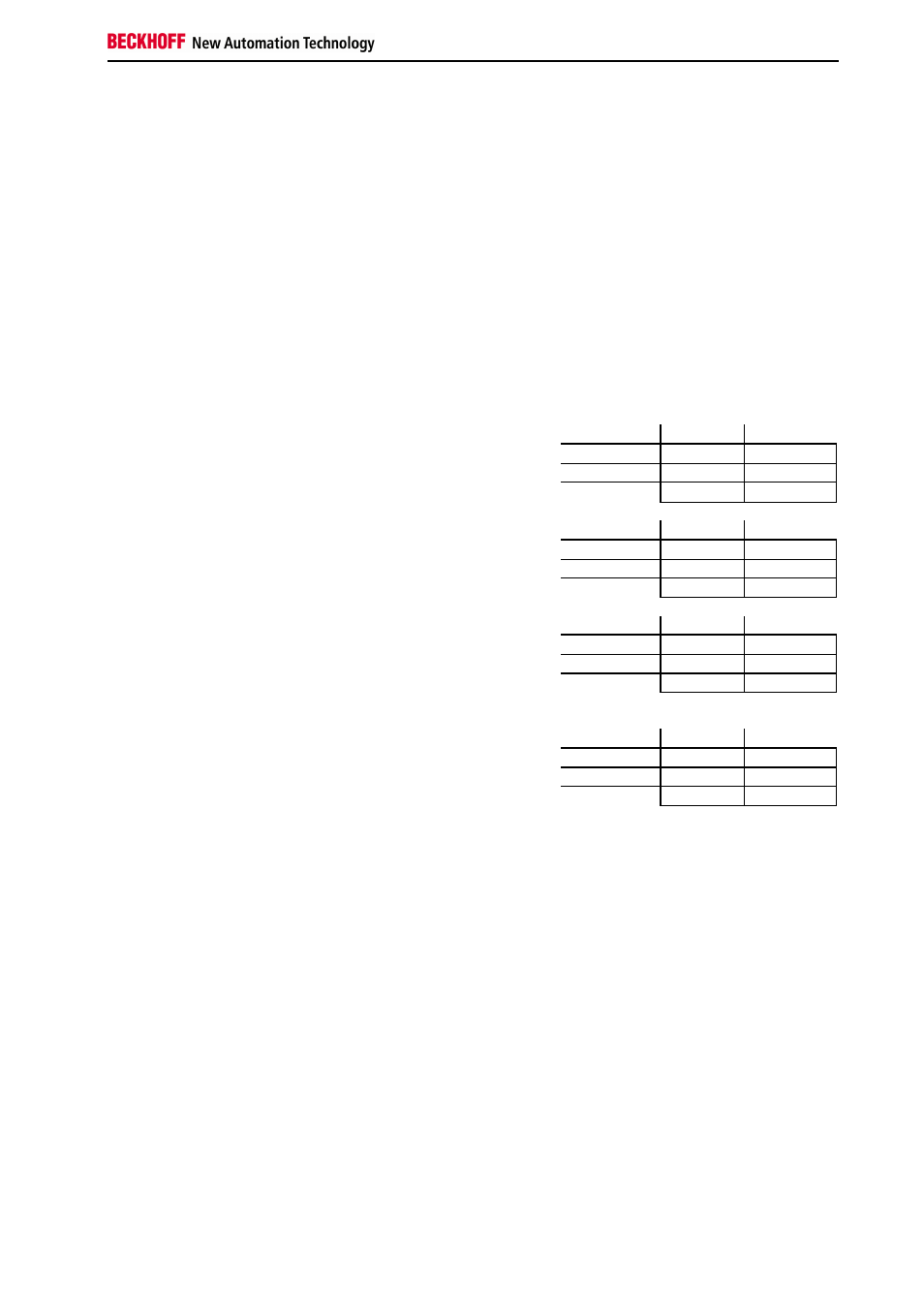
4.1 Mapping in the bus coupler
Standard Format
In the Standard format the KL1501 is mapped in the bus coupler with 5
bytes input and 5 bytes output data.
Conditions
Word offset High Byte
Low Byte
0
D0
CB/SB
1
D2
D1
Default Mapping for CAN,
DeviceNet, ControlNet,
Modbus, RS232 and
RS485 Coupler
Complete evaluation:
don’t care
Motorola format:
no
Word alignment:
no
2
res.
D3
Conditions
Word offset High Byte
Low Byte
0
D3
CB/SB
1
D1
D2
Default-Mapping for
Profibus and Interbus
Coupler
Complete evaluation:
don’t care
Motorola format:
yes
Word alignment:
no
2
res.
D0
Conditions
Word offset High Byte
Low Byte
0
res.
CB/SB
1
D1
D0
Complete evaluation:
don’t care
Motorola format:
no
Word alignment:
yes
2
D3
D2
Default-Mapping for
Lightbus and Ethernet
Coupler and
Bus Terminal Controller
(BCxxxx, BXxxxx)
Conditions
Word offset High Byte
Low Byte
0
res.
CB/SB
1
D2
D3
Complete evaluation:
don’t care
Motorola format:
yes
Word alignment:
yes
2
D0
D1