BECKHOFF BC3100 User Manual
Page 46
Annex
46
BC3100
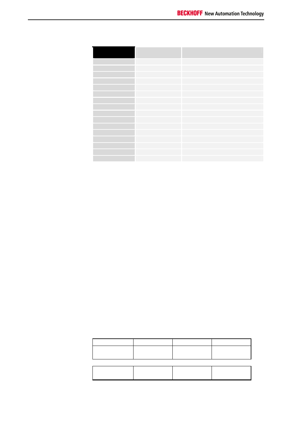
Part for bit-oriented data, digital inputs:
Position in
block
PLC Task
Process Image
Description
POS02
IX40.0
Input signal 1st channel
POS02
IX40.1
Input signal 2nd channel
POS03
IX40.2
Input signal 1st channel
POS03
IX40.3
Input signal 2nd channel
POS04
IX40.4
Input signal 1st channel
POS04
IX40.5
Input signal 2nd channel
POS05
IX40.6
Input signal 1st channel
POS05
IX40.7
Input signal 2nd channel
POS06
IX41.0
Input signal 1st channel
POS06
IX41.1
Input signal 2nd channel
POS15
IX41.2
Input signal 1st channel
POS15
IX41.3
Input signal 2nd channel
POS16
IX41.4
Input signal 1st channel
POS16
IX41.5
Input signal 2nd channel
POS17
IX41.6
Input signal 1st channel
POS17
IX41.7
Input signal 2nd channel
Representation of analog signals in the
process image
In the standard case, analog signals present themselves as follows: two
input bytes or two output bytes of the process image are needed for each
analog channel. The two bytes represent the value as an unsigned integer,
i.e. 15 bits with a sign. The data format is used independently of the actual
resolution. For example: with a resolution of 12 bits for analog values in the
positive and negative value ranges the four least significant bits are of no
significance.
If the value of the analog signal is only positive, the sign bit (bit 15 MSB) is
always "0". In this case, the 12 bits of the analog value are reproduced in
bits 14 to 3. The three least significant bits are of no relevance.
Via the configuration interface, it is possible to set the bus controller so that
it represents all or individual analog channels in an extended mode.
Optionally, the control and status byte of a channel can also be displayed.
The least significant bit of three bytes has control and status functions. The
further two bytes become inputs and outputs. Various modes can be set
with the control byte. The six least significant bits of the control and status
byte can be used as addressing bits. Addressing serves to write and read a
register set inside the terminal. The register set has 64 registers. The
settings are stored in a power fail safe manner.
Offset 0
Offset 1
Offset 2
Offset 3
I/O bytes of an analog
channel
Control byte
Blank
Output word
Low byte
Output word
High byte
in the process image of the
PLC task
Status byte
Blank
Input word
Low byte
Input word
High byte