Run and reaction times, Basic information, Bc3100 – BECKHOFF BC3100 User Manual
Page 17
Basic information
BC3100
17
Field bus error
The red BF LED on the bus terminal controller lights up whenever the
BC3100 is not participating in the Profibus-DP exchange of data.
PLC-RUN
The Green RUN LED on the bus terminal controller lights up whenever the
PLC task is in the RUN state.
PLC
program
in
flash
memories
When the PLC program is downloaded with the TwinCAT PLC
programming environment, the program is initially stored only in the RAM.
The program is transferred from the RAM to the flash memory by means of
the Online -> Create a boot project command. The red DIA LED on the bus
terminal controller goes on during this storage operation.
Run and reaction times
Cycle time of the PLC task
The PLC task is called up cyclically and time-controlled, whereby the cycle
time can be set via the configuration interface (default time: 5 ms). The
minimum cycle time is 1 ms. 20% of the timing resources should be
reserved for execution of the background processes. The PLC task's run
time is composed of the data exchange via the K-bus, the operating
system of the PLC task and the actual PLC program.
The PLC task's run time can be measured with the KS2000 configuration
software. The nominal cycle time and the time for background execution
can then be set on the basis of this measurement.
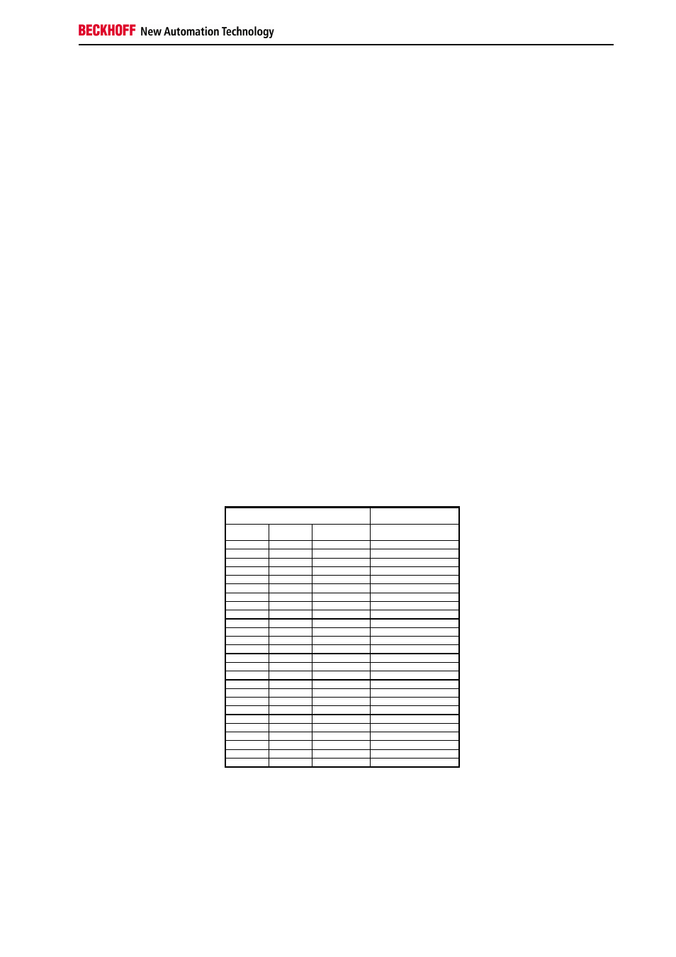
K-bus reaction time
The reaction time on the K-bus is determined by shifting and saving of the
data. The following table contains measured values for typical setups. It is
possible to extrapolate to larger numbers.
Terminals inserted on the bus terminal
controller
Run time on the K-bus
Digital
OUT
Digital
IN
Analog
IN/OUT
T_cycle
(us)
4
0
0
150
8
0
0
170
12
0
0
170
16
0
0
200
20
0
0
200
24
0
0
220
28
0
0
220
32
0
0
245
0
4
0
150
0
8
0
180
0
12
0
180
0
16
0
200
0
20
0
200
0
24
0
230
0
28
0
230
0
32
0
250
4
4
0
170
8
8
0
195
12
12
0
220
16
16
0
250
20
20
0
275
24
24
0
300
28
28
0
325
32
32
0
350
4
4
1 (KL3202)
630
4
4
2 (KL3202)
700