BECKHOFF BC3100 User Manual
Page 36
PROFIBUS bus terminal controller BC3100
36
BC3100
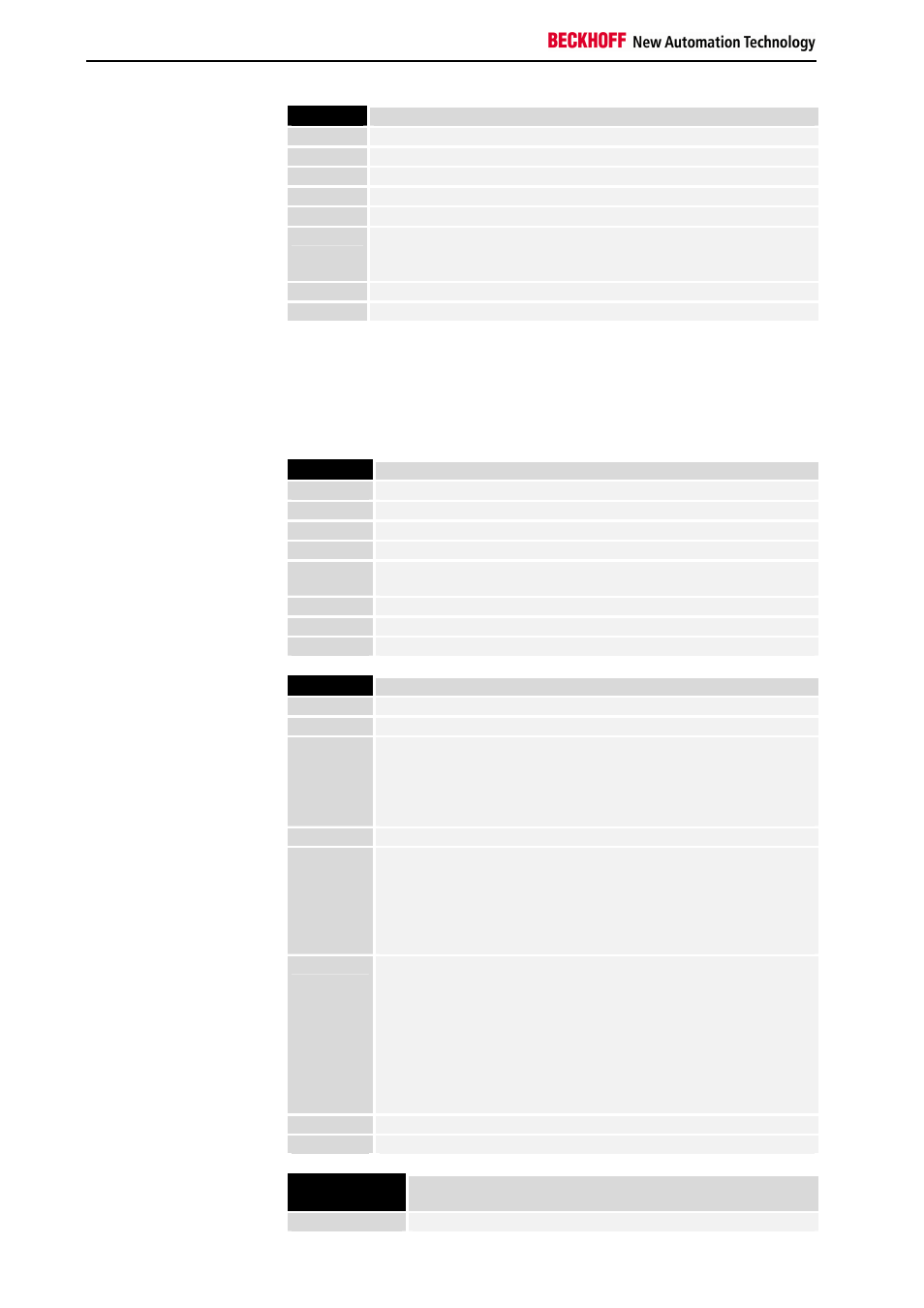
Byte No
Description
Byte 0
Terminal No (1-64)
Byte 1
Channel No (1-4)
Byte 2
PLC process image, low byte address
Byte 3
PLC process image, high byte address
Byte 4
PLC process image bit address
Byte 5
Analog terminals: status byte of the terminal
Digital terminals: bit 1: short circuit channel 0
short circuit channel 1
Byte 6
(reserved for expansions)
Byte 7
(reserved for expansions)
The PLC process image addresses are entered only if the corresponding
tables have been transferred (see Table 80 in the bus coupler).
Diagnostics messages of
the bus coupler
Besides the diagnostics messages of the terminals, there are also 2
diagnostics messages of the bus coupler.
Byte No
Description
Byte 0
0
Byte 1
0
Byte 2
Initialisation error
Byte 3
Terminal bus error
Byte 4
Invalid test on bus reset or invalid terminal number in the event of a
terminal bus error
Byte 5
Invalid terminal number on bus reset
Byte 6
First terminal number not supported
Byte 7
0
Byte No
Description
Byte 0
0
Byte 1
255
Byte 2
UserPrmData error
0: No error
1: Reserved
2: Input or output data too long
3: Invalid byte or word of the UserPrmData
Byte 3
First invalid byte or word of the UserPrmData
Byte 4
CfgData error
0: No error,
1: Not enough CfgData,
2: Invalid CfgData byte,
3: Error generating the DP process image
4: Error generating the PLC process image (BC3100 only)
Byte 5
Byte 4 = 2:
First invalid byte of the CfgData (0 - 63)
Byte 4 = 3:
0: Maximum input or output length exceeded
2: Compile buffer in the case of the DP process image is too small
Byte 4 = 4:
0: Maximum input or output length exceeded
2: Compile buffer in the case of the PLC process image is too small
(BC 3100 only)
Byte 6
0
Byte 7
0
Initialisation
error
Description
Bit 0
Error reading out the EEPROMs