Connections, Power supply 100-240 v ac, Digital video connection – BECKHOFF CP6003 User Manual
Page 6: Analog video connection
Eiserstraße 5 / D-33415 Verl / Phone 05246/963-0 / Fax 05246/963-149
6
Operating Instructions
Control Panel CP6003
CP6003
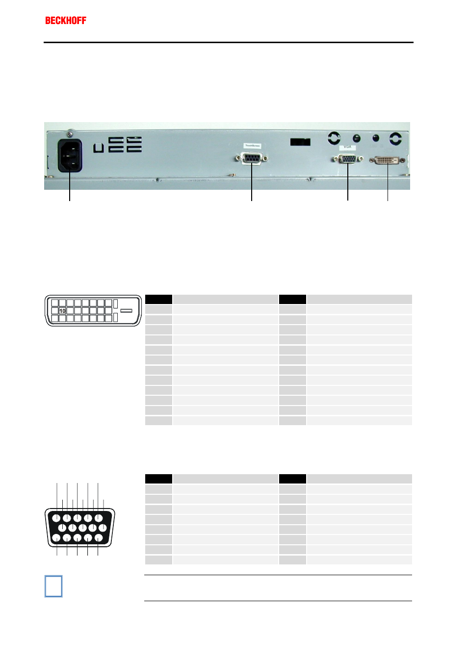
Connections
The connections are located at the rear of the Control Panel (see
photograph below).
1. Power supply 100-240 V AC
Power supply
Connect an external power supply unit (100-240V AC 50-60Hz) to this
appliance socket.
2. Digital video connection
Digital video connection
If your PC has a graphic card with a 24-pin DVI connector, you should
connect it with a Digital 24-pin DVI signal cable.
Pin
Signal Assignment
Pin
Signal Assignment
1
T.M.D.S. Data 2-
13
T.M.D.S. Data 3+
2
T.M.D.S. Data 2+
14
+5V Power
3
T.M.D.S. Data 2/4 Shield
15
Ground (for +5V)
4
T.M.D.S. Data 4-
16
Hot Plug Detect
5
T.M.D.S. Data 4+
17
T.M.D.S. Data 0-
6
DDC Clock
18
T.M.D.S. Data 0+
7
DDC Data
19
T.M.D.S. Data 0/5 Shield
8
No Connect
20
T.M.D.S. Data 5-
9
T.M.D.S. Data 1-
21
T.M.D.S. Data 5+
10
T.M.D.S. Data 1+
22
T.M.D.S. Clock Shield
11
T.M.D.S. Data 1/3 Shield
23
T.M.D.S. Clock+
1 2 3 4 5 6 7 8
9
11 12 13 14 15 16
17 18 19 20 21 22 23 24
12
T.M.D.S. Data 3-
24
T.M.D.S. Clock-
3. Analog video connection
Analog video connections
The Control Panel has one 15-pin sub-D VGA signal input. You can plug
the VGA cable into this video connection.
Pin
Signal Assignment
Pin
Signal Assignment
1
Video signal red
9
Code (no pin)
2
Video signal green
10
Ground synchronisation
3
Video signal blue
11
Display ID Bit 0
4
Display ID Bit 2
12
Display ID Bit 1
5
Ground
13
Horizontal synchronisation
6
Ground red
14
Vertical synchronisation
7
Ground green
15
Display ID Bit 3
1
10 9 8 7 6
2
3
4
5
11
12
13
14
15
8
Ground blue
i
Note
If both analog and digital input ports are connected at the same time,
the signal input can be selected with the
menu.
1
4
3
2