BECKHOFF C9900-G0xx User Manual
Page 16
Product description
14
C9900-G0xx
2.4.2 Configuration
Each configuration features an emergency stop PCB, which contains the USB K-bus coupler. The
remainder of the configuration of the three- and four-button PCBs depends on the display size. Some
examples are shown in Table 4 examples below. A detailed list of combinations can be found in the
annex in section 7.3.
Designation
Number of
Keys
Alignment
Emergency stop
PCB
Three-button
PCB
Four-button
PCB
C9900-G022 4 Horizontal
● -
●
C9900-G023 7 Horizontal
●
●
●
C9900-G024 8 Horizontal
● -
●●
…
C9900-G027 13 Horizontal
●
●●●
●
Table 4: Button PCB combinations
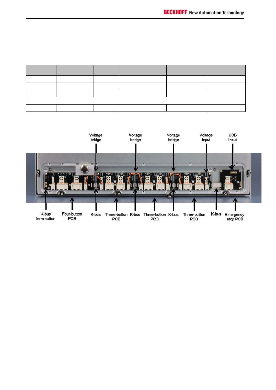
Fig. 9 shows a possible configuration and the factory state, using the CP2924-0000-G007 as an example.
Fig. 9: Rear view of CP2924-0000-G007
USB input
The USB input is located on the emergency stop PCB. The push-button extension is controlled via the
USB port of the CP39xx/CP2xxx. The USB input is pre-wired in the factory.
K-bus
The conversion from USB to K-bus takes place on the emergency stop PCB. The button PCBs are
connected via the K-bus interface of the emergency stop PCB. Each button PCB has a K-bus input and a
K-bus output. The last button PCB is terminated with a jumper at the K-bus output. The K-bus wiring of
the PCBs is done in the factory.
Power supply
The button PCBs are supplied via the voltage input of the first button PCB, from where the power supply
is looped to the next button PCB with a connecting cable, and so on. The connecting cables are provided
ex factory. The wiring of the voltage input is done by the customer.
Connector strips
On the PCBs connection strips are available so that the signals can be used for additional purposes. The
wiring is done by the customer.