BECKHOFF C9900-G0xx User Manual
Page 15
Product description
C9900-G0xx
13
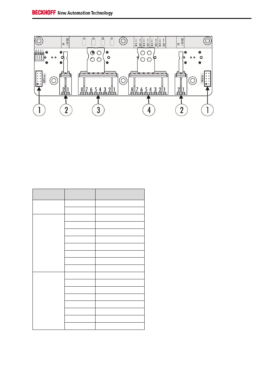
Four-button PCB
Fig. 8: Four-button PCB
The four-button PCB also has two K-bus interfaces (1, CON400 & CON401), which are assigned ex
factory. The outer connection strips (2, CON600 & CON601) are used for power supply for the indicator
lamps, connection strip 4 is available for customer use. The bridges between the button PCBs are
assigned ex factory. The power supply has to be provided by the customer. One of the two N/O contacts
of each button is available for customer use via a connection strip (3, CON603). At a further connection
strip (4, CON604) four digital inputs are available for customer use, which are transferred via the K-bus.
The 24 V supply has to be provided by the customer. The PCB also features a DIP switch (5, SW600),
which is explained in section 2.5.
The pin assignments for connection strips 2, 3 and 4 are listed in Table 3.
Connection
strip
Terminal
point
Description
1
1
24 V DC
2 0
V
3
1
Input N/O contact 1
2
Output N/O contact 1
3
Input N/O contact 2
4
Output N/O contact 2
5
Input N/O contact 3
6
Output N/O contact 3
7
Input N/O contact 4
8
Output N/O contact 4
4
1
24 V output
2
Digital input 1
3
24 V output
4
Digital input 2
5
24 V output
6
Digital input 3
7
24 V output
8
Digital input 4
Table 3: Pin assignment for four-button PCB