BDI 9950 Vista User Manual
Page 3
3
assembly
instructions
bdiusa
.
com
customerservice
@
bdiusa
.
com
Step 9
Install Back Cover Panel
When all wires are in place and secured, install
Back Cover Panel (FB) using 2 remaining 5/8” long
Phillips Head Screws (G). Carefully, move Vista into
place by pulling and lifting on lower shelf bracket
elbows. Adjust glides if necessary.
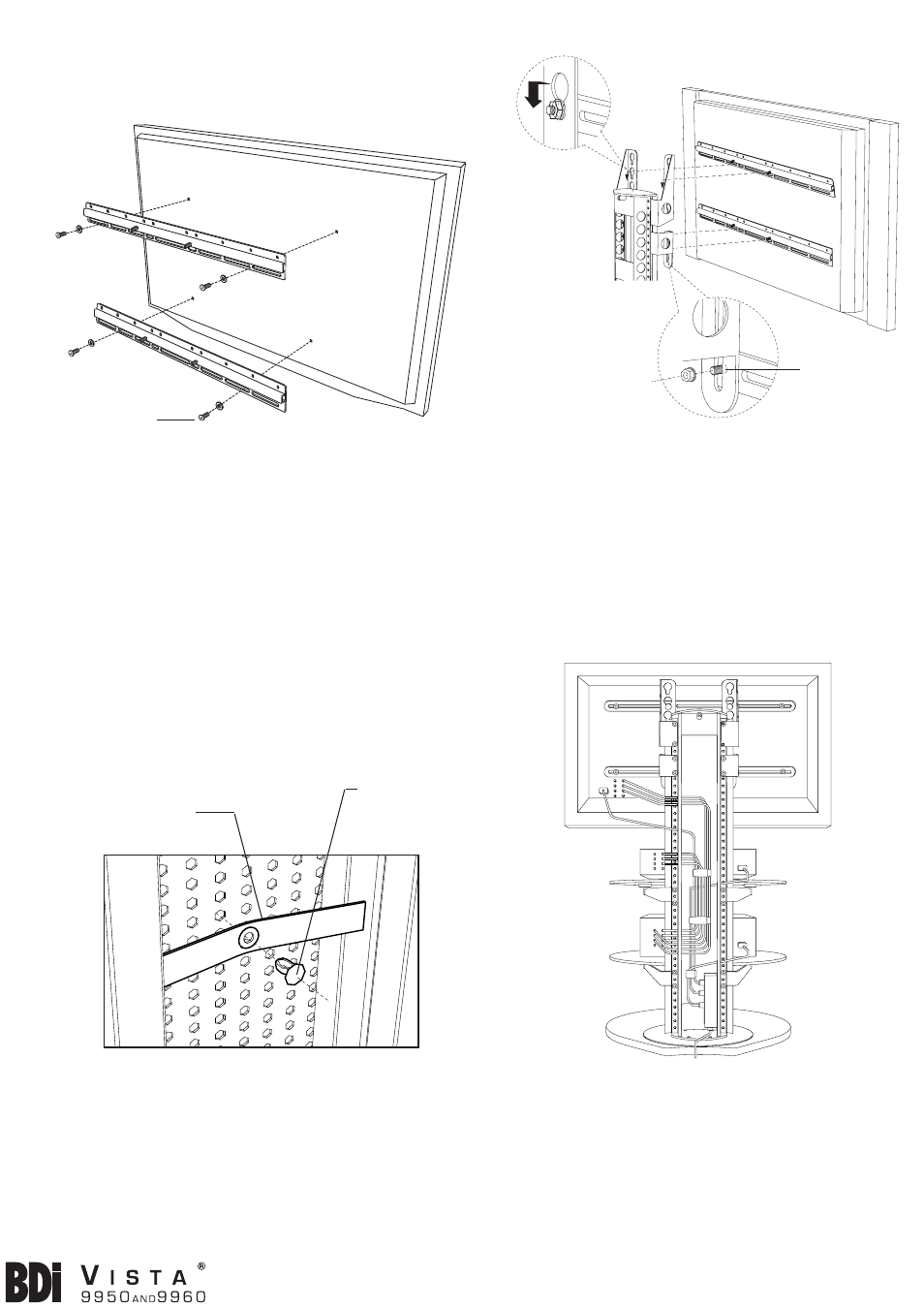
Step 8
Install Wire Management Straps
Wire Management Straps (Q) attach to the
perforated metal panel inside the Vista spine simply
by pushing the Plastic Pin (R) into the hole in the
center of the strap and into one of the holes on
the panel (Figure 7). Wrap straps around cords as
shown (Figure 8). Straps may be relocated simply by
pulling out and pushing plastic pin into another hole.
Q - Wire Management
Strap x 3
Flat Screen TV
(back view)
Short Mounting
Screws (V)
Washers (L)
Threaded stud
Pre-threaded
Nut (M) to
upper UMB
bar.
Nut
(M)
Step 6
Install Horizontal Mounting Bars
Find mounting screws that came with your flat
screen TV. If screws are not available, find the
Short Phillips Head Mounting Screws (V) provided
with Vista that thread cleanly into the mounting
holes in the back of your TV. The following thread
sizes are included: M5, M6, M8, 10-32 & 1/4-28.
Attach both Horizontal Mounting Bar (S) to TV as
shown (Figure 5) using Washers (L) and Phillips
driver. Note: If back of TV has a curved surface, or,
if bars do not sit flat, use Spacers (T or U) and Long
Mounting Screws (V) provided. Make sure bars are
centered left to right! Button hooks should be on top
and threaded studs on bottom. Fully tighten bars to
TV!
Figure 4
Figure 7
Figure 5
Step 7
Attach flat screen TV
Carefully “hook” TV onto screen brackets as shown
(Figure 6). Make sure both pre-threaded nuts drop
into key hole slot and that threaded studs go into slot
on Bottom Screen Brackets (HBL & HBR). Tighten
Nuts (M) using wrench. Note: Vista will support flat
screens up to 225lbs (102kg). Note: Vista is NOT
designed to support televsions greater than 6” in
depth.
Figure 6
R - Plastic Pin
x 3