BDI 8224 MIRAGE User Manual
Page 2
2
assembly
instructions
bdiusa
.
com
customerservice
@
bdiusa
.
com
3
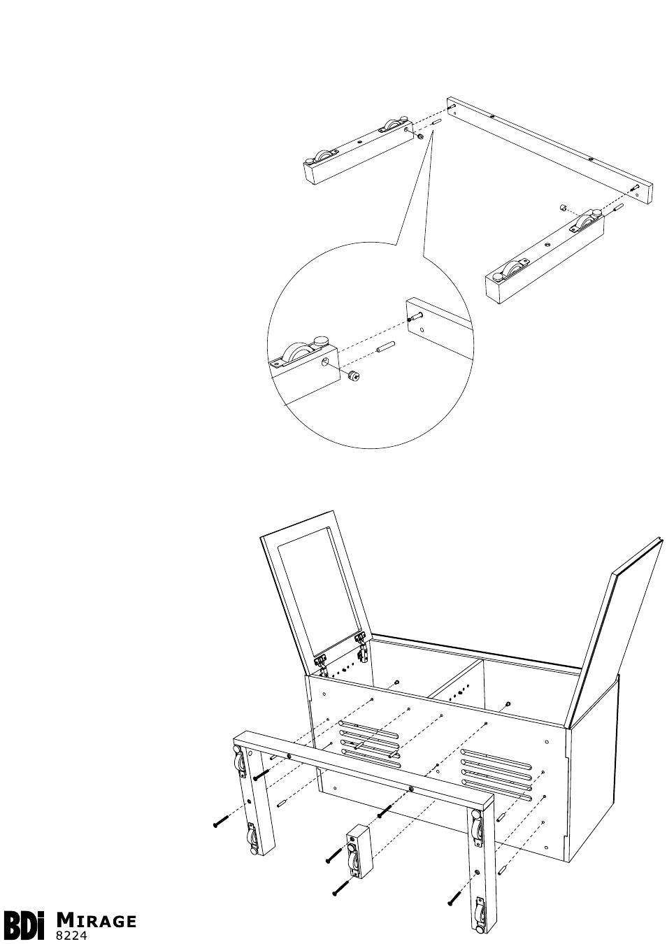
Step 3
Build Base Assembly
Press Dowel Pins (C) into place at indicated locations near ends of
Front Rail (G), then install Cam Bolts (D) at indicated locations using
provided Phillips Screwdriver (A). Then join the Front
Rail (G) and Leg Assemblies (F) together,
aligning holes for Cam Bolts (D) and Dowel
Pins (C).
Once Dowel Pins (C) and Cam Bolts (D)
are fully inserted into the respective holes,
fasten together by inserting Cam Fastener
(E) and turning it approximately one-half
turn clockwise using
Phillips Screwdriver (A).
Step 4
Install Base Assembly and Center Leg
With Assembled Cabinet (L) resting safely on its back surface,
press Dowel Pins (C) into place at six (6) indicated locations of
cabinet bottom. Then install built Base
Assembly to Cabinet bottom using
M6 x 70mm Bolts (H) and Barrel
Nuts (J), and tighten with Phillips
Screwdriver (A). Next install Center
Leg (K) to Cabinet bottom using M6 x
73mm Bolts (I) and Barrel Nuts (J),
and tighten with Phillips Screwdriver
(A).
NOTE: As Barrel Nuts (J) are
preinstalled on ends of M6 x 70mm
Bolts (H) and M6 x 73mm Bolts
(I), first loosen and remove Barrel
Nuts from Bolts, then insert Bolts
through the Base Assembly and
Center Leg from bottom, fastening
into place with Barrel Nuts from
the top (inside cabinet).
E
C
D
F
G
H
H
H
H
I
I
C
C
C
C
C
C
I
I