Instructions, Warning – Basler Electric ESD202 User Manual
Page 2
Publication
9290500990
Revision
B
Instructions
Date
10/12
Page
2 of 2
For terms of service relating to this product and software, see the Commercial Terms of Products and Services document available at
www.basler.com/terms
.
INSTALLATION
Warning!
Perform the discharging procedure before
handling the ESD202.
An ESD202 should be used with a single circuit
breaker. Control of more than one breaker (or other
devices) by a single ESD202 is not recommended. If
control of more than one breaker is desired, it must be
demonstrated, through independent testing, that
combinations of breakers (or other devices) can be
reliably operated from a single ESD202.
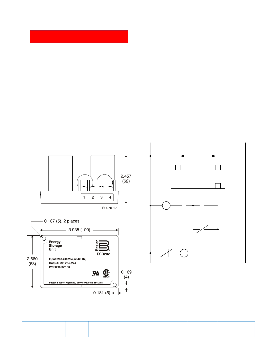
Mounting
ESD202 mounting dimensions are illustrated in Figure
1. Dimensions are given in inches with millimeters in
parenthesis.
Connections
Typical ESD202 connections are shown in Figure 2.
ESD202 terminals accommodate a maximum wire
size of 12 AWG (3.31 mm
2
). The terminal screws have
a maximum torque rating of 9 in-lb (1 N
m).
STORAGE AND MAINTENANCE
This device contains long-life, aluminum electrolytic
capacitors. For devices that are not in service (spares
in storage), the life of these capacitors can be
maximized by energizing the device for 30 minutes
once per year.
No maintenance of the ESD202 is required other than
periodically checking that all connections are clean
and tight. The ESD202 is not field repairable. If repairs
are required, return the ESD202 to Basler Electric.
Figure 1. ESD202 Mounting Dimensions
Figure 2. ESD202 Typical Connections
52 CS/T
52a
50/51
86
52TC
86
86
ESD202
3
1
4
240 Vac
Legend
50/51:
Overcurrent Relay
52:
Power Circuit Breaker
86:
Lockout Relay
a:
Breaker Auxiliary Contact
CS/T:
Control Switch, Trip
P0070-18