Basler Electric VR63-4B User Manual
Page 2
b.
Ensure that the regulator is correctly
connected to the generator. See
Interconnection Diagram.
c.
Install fuses per FUSES paragraph.
d.
Set the regulator voltage control fully
CCW and the Stability Potentiometer to
mid-range.
SYSTEM START-UP
a.
Start the prime mover and bring up to
rated speed. Voltage should buildup. If a
minimum residual of 10V is not present,
perform field flashing.
b.
Slowly adjust voltage control until voltage
reaches nominal value.
OPERATIONAL TEST
a. Connect the test setup as shown in
Operational Test. Do not apply power.
b.
Adjust regulator voltage adjust to
maximum CCW.
c.
Apply 240V, 60 Hz power to regulator.
RESULT: Light bulb flashes momentarily.
d.
Slowly adjust the regulator voltage adjsut
CW.
RESULT:
1) Before the full CW position is reached, the
light bulb reaches full brilliance to signify the
regulating point.
2) At the regulating point, a small change in
the voltage adjust should turn the light bulb on
or off.
FIELD FLASHING
When the regulator is operated with the
generator for the first time, the polarity of
residual magnetism may not correct or the
magnitude not enough. If the generator does
not build-up after startup, shut down the prime
mover and proceed with the following steps:
a.
With the prime mover at rest, apply a dc
source (not grounded) of not more than
12V, to terminals F+(positive) and F-
(negative) in series with a limiting resistor
of 3-5 ohms.
b.
Allow approximately 3 seconds before
removing the dc source.
c.
Start prime mover and measure voltage
at regulator leads 3 and 4. If voltage is
greater than 10 volts, voltage build-up
should be successful. Repeat field
flashing procedure if less than 10 V
residual is measured.
d.
If repeating steps 1 and 2 does not result
in generator voltage build-up, replace the
voltage regulator.
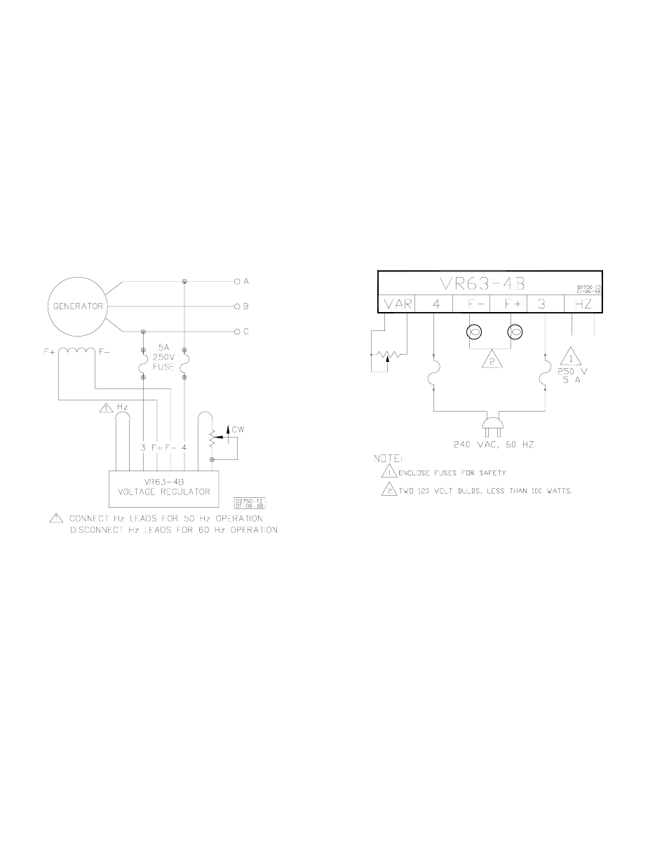
Interconnection Diagram, 208/240 V Nominal
Operational Test