Instructions – Basler Electric APR63-5 User Manual
Page 3
FIELD FLASHING
When the generator is operated with the regulator for
the first time, the polarity of the generator’s residual
magnetism may not be correct or the magnitude may
not be enough for reliable voltage buildup. If the
generator voltage does not build up, stop the prime
mover and proceed as follows:
1.
With the prime mover at rest, apply an
ungrounded dc source of not more than
48 Vdc to terminals F+ and F– in series with a
limiting resistor. Use 1
Ω of resistance for
each volt from the dc source. The resistor
should have a power rating of at least 1 watt
per volt.
2.
Allow approximately 30 seconds to elapse
before removing the dc source.
3.
Start the prime mover and measure the
voltage at regulator terminals 3 and 4. If the
voltage is greater than 6 Vac, voltage buildup
should occur. Repeat the flashing procedure if
less than 6 Vac is measured.
OPERATIONAL TEST
If desired, perform the following steps to perform a
bench test of APR 63-5 operation.
1.
Connect the APR 63-5 and apply 240 Vac as
shown in Figure 7.
2.
Rotate the VOLT control fully counter-
clockwise. The lamp should not be lit.
3.
Rotate the VOLT control fully clockwise. The
lamp should be lit.
4.
Rotate the VOLT control counterclockwise
until the lamp turns off.
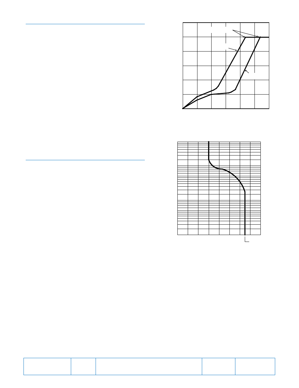
Figure 1. Frequency Compensation Curves
Figure 2. Typical Inverse Time Characteristic Curve
0
0
10
20
30
40
50
60
20
40
60
80
100
120
Frequency (Hz)
(%
F
ro
m
N
o
m
in
a
l)
G
e
n
e
ra
to
r
O
u
tp
u
t
D2717-05
50 Hz
60 Hz
“Corner Frequency”
T
im
e
D
e
la
y
(
s
e
c
o
n
d
s
)
Field Voltage (dc)
1
2
3
4
5
6
8
10
20
30
40
50
60
80
100
70
200
300
400
500
80
90
100
110
120
130
140
150
135 ±5
D2717-06
Publication
9168700991
Revision
G
Instructions
Date
04/14
Page
3 of 6